
Steam generator

a generator and steam technology, applied in the field of steam generators, can solve the problems of more complex designs of steam generators, and achieve the effects of facilitating transportation and installation of steam generators, facilitating maintenance of described steam generators, and reducing the complexity of steam generators

Active Publication Date: 2020-02-11
ROLLS ROYCE PLC +1
View PDF7 Cites 0 Cited by
  • Summary
  • Abstract
  • Description
  • Claims
  • Application Information

AI Technical Summary

Benefits of technology

The inventor has taken the step of creating a modular arrangement of a conduit, which allows for easier transportation and installation of large steam generators. The pressure of the primary fluid helps keep the modules connected, reducing the risk of leakage to the secondary fluid flow. This also makes maintenance easier because a single module can be inspected or replaced as needed. Overall, this innovation improves the efficiency and flexibility of steam generator design and installation.

Problems solved by technology

As such, the person skilled in the art would be prejudiced against a modular arrangement of the conduit.
Moreover, the modular arrangement may allow for more complex designs of steam generator.

Method used


Image

  • Steam generator
  • Steam generator
  • Steam generator

Examples


Embodiment Construction

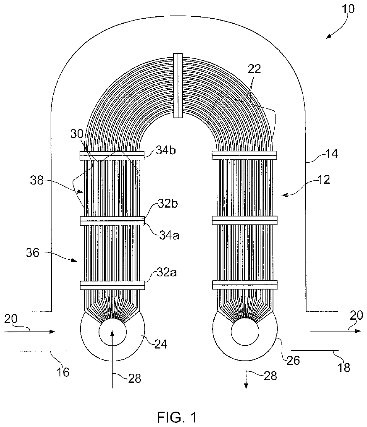
[0047]Referring to FIG. 1 a steam generator is indicated generally at 10. The steam generator includes a conduit bundle 12 partially contained within a vessel 14. The vessel 14 includes an inlet 16 and an outlet 18. In the present embodiment, the vessel is formed using conventional methods and design, so will not be described in more detail here. In use, a primary fluid flow (indicated by arrow 20) enters the steam generator through the inlet 16, flows through the vessel 14 and exits the steam generator though outlet 18.

[0048]The conduit bundle 12 includes a plurality of conduits 22. The conduits are arranged so that an inlet of each conduit connects to an inlet header 24 and an outlet of each conduit connects to an outlet header 26. In use, a secondary fluid flow (indicated by arrow 28) flows through the conduit bundle, entering each conduit of the bundle at the inlet header 24 and exiting each conduit of the bundle at the outlet header 26.

[0049]As will be understood by those skill...


PUM


Abstract

A steam generator comprising a vessel having an inlet and an outlet, and in use a primary fluid flow enters the vessel through the inlet and exits the vessel through the outlet. A plurality of modules are connected in series and at least partially housed within the vessel, and each module comprises at least one tube. The modules are arranged such that at least one tube of one module is coaxial with at least one tube of an adjacent module so as to define a conduit through which a secondary fluid can flow from one module to an adjacent module.

Description

FIELD OF INVENTION[0001]The present invention relates to a steam generator and / or a steam generator system.BACKGROUND[0002]There are numerous different types of steam generators used for multiple functions. One such function is use in a pressurised water reactor (often referred to as a PWR). When used in a PWR, primary coolant is used to transport heat between a reactor core and a steam generator. In the steam generator, the primary coolant is cooled by a secondary coolant, or in other words a secondary coolant is heated and converted to steam by the primary coolant. Once heated, the secondary coolant is used to turn a turbine which is connected to a generator to generate electricity.[0003]Generally, the steam generator will include a bundle of tubes at least partially contained within a vessel. The primary coolant may be supplied to the tubes and the secondary fluid may be supplied to the vessel, or vice-versa. The wall of the tubes separates the primary coolant from the secondary ...

Claims


Application Information

Patent Timeline
Patent Type & Authority Patents(United States)
IPC IPC(8): G21C19/28F22B21/30F22B1/16F22B21/12G21D1/00
CPCF22B1/162F22B21/126F22B21/30G21D1/006F22B21/26F22B37/001F28F1/00F28F9/26
Inventor BUNCE, IAN MICHAELTOWN, NIGEL ALASTAIRCAUSTON, MARK ALWYN THOMASBLAKE, MATTHEW CHARLESMILLS, DAVID WILLIAM
Owner ROLLS ROYCE PLC
Learn More