Heater control device

Pending Publication Date: 2022-02-10
TOYOTA JIDOSHA KK
View PDF0 Cites 0 Cited by
  • Summary
  • Abstract
  • Description
  • Claims
  • Application Information

AI Technical Summary

Benefits of technology

The present disclosure provides a heater control device for vehicles that can prevent fogging of the image capturing transparent region without requiring a sensor to detect the glass temperature. The device includes a camera sensor to capture images through the transparent region, a camera heater to generate heat and heat the transparent region, and a control unit to estimate the dew-point temperature of the transparent region and determine the defogging electric power required to maintain the temperature of the transparent region at the target temperature. The device can prevent the temperature of the transparent region from falling below the dew-point temperature and thus prevent fogging, while also reducing the possibility of wasting electric power. The device does not require a sensor to detect the temperature of the transparent region, which reduces manufacturing costs.

Problems solved by technology

When the image capturing transparent region is fogged, the camera sensor captures the fogging, and cannot accurately capture an image of the outside of the vehicle.
As a result, there is a possibility that the related-art device cannot remove or prevent the fogging of the image capturing transparent region, and there is also a possibility that the related-art device increases the glass temperature to a temperature that is too high with respect to the dew-point temperature, and thus consumes wasteful electric power.
Further, the related-art device is required to include a sensor for detecting the glass temperature, and a manufacturing cost thereof consequently increases.

Method used


Image

  • Heater control device
  • Heater control device
  • Heater control device

Examples


operation example

[0046]With reference to FIG. 5, description is given of an operation example of this control device 10.

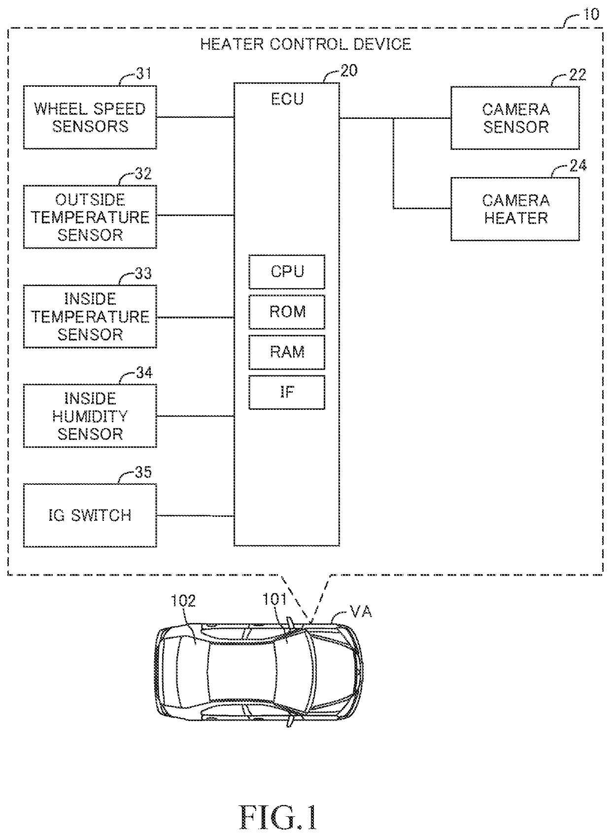
[0047]As described above, the ECU 20 determines whether or not the execution condition for the defogging control is satisfied at a time “ts” at which the IG switch 35 is set to the ON position. This execution condition is a condition that the outside temperature Ta is equal to or lower than a threshold temperature Tath. For example, the threshold temperature Tath is set in advance to a dew-point temperature (10° C.) at the time when the inside temperature Tb is a predetermined temperature (25° C.) and the inside humidity H is a predetermined humidity (40%).

[0048]The ECU 20 starts the defogging control when the execution condition is satisfied. In the example of FIG. 5, the ECU 20 determines that the execution condition is satisfied at the time “ts”, and thus starts the defogging control.

[0049]In the defogging control, the ECU 20 divides a unit period Tcyc into an OFF period (non-en...

first modification example

[0092]In a first modification example, the voltage Vc to be applied to the camera heater 24 is variable, and the ECU 30 determines the voltage Vc so that the camera heater 24 is energized at the defogging electric power Wc.

[0093]In the first modification example, a voltage determination routine for determining the voltage Vc is executed in place of the duty ratio determination routine. Further, the camera heater energization control in the first modification example is different from that in the at least one embodiment in a point that the energization control is not executed in accordance with the OFF period Toff and the ON period Ton, but the voltage Vc determined by the voltage determination routine is applied to the camera heater 24.

[0094]

[0095]With reference to FIG. 8, description is now given of the voltage determination routine in the first modification example. In FIG. 8, a step in which the same processing as that of the step of FIG. 6 is executed is denoted by the same refe...

second modification example

[0100]In the at least one embodiment, the CPU may apply “a target temperature Ttgt obtained by adding a predetermined temperature (for example, 2° C.) to the dew-point temperature Td” in place of the dew-point temperature Td, to Expression (4), to thereby determine the duty ratio D. The target temperature Ttgt is only required to be a value equal to or higher than the dew-point temperature Td, and the target temperature Ttgt may be the dew-point temperature Td. Thus, it can also be described that the at least one embodiment uses the dew-point temperature Td as the target temperature Ttgt. In the first modification example, the CPU may apply the target temperature Ttgt in place of the dew-point temperature Td to Expression (7), to thereby determine the voltage Vc.


PUM


Abstract

A heater control device includes a camera sensor configured to capture an image of an outside of a vehicle through an image capturing transparent region of a window glass, and a camera heater configured to heat the image capturing transparent region. The heater control device is configured to: apply, to a correlation which is set in advance between an outside temperature, a vehicle speed, and energization electric power, and a temperature of the image capturing transparent region corresponding to the outside temperature, the vehicle speed, and the energization electric power, the outside temperature at a current time, the vehicle speed at the current time, and a target temperature equal to or higher than a dew-point temperature, to thereby determine defogging electric power so that the temperature of the image capturing transparent region is prevented from falling below the dew-point temperature.

Description

BACKGROUNDTechnical Field[0001]The present disclosure relates to a heater control device which includes a camera sensor configured to capture an image of an outside of a window glass from an inside of the window glass through an image capturing transparent region being a part of the window glass of a vehicle and a camera heater configured to heat the image capturing transparent region by being energized, and is configured to control the energization to the camera heater.Related Art[0002]Hitherto, there has been known a heater control device configured to control energization to a heater configured to heat a window glass of a vehicle. This heater generates heat by being energized.[0003]A heater control device described in Japanese Patent Application Laid-open No. 2017-114154 (hereinafter referred to as “related-art device”) controls energization to a heater for heating a window glass (front window).[0004]The related-art device executes deicing control of energizing the heater in orde...

Claims


Application Information

Patent Timeline
IPC IPC(8): H05B1/02B60S1/02H05B3/84
CPCH05B1/0236H05B2203/035H05B3/84B60S1/026B60S1/0848
Inventor ADACHI, TAKAHIRONAKAJIMA, TATSUYOSHIMIYADOH, TAKAHIRO
Owner TOYOTA JIDOSHA KK
Why Eureka
Try Eureka