
Network Node, Computer Program, Computer-Readable Medium and Method for Fail-Safe Data Transmission

a network node and data transmission technology, applied in data switching networks, program control, instruments, etc., can solve the problems of affecting the reliability of the network, and the failure of the data transmission in ethernet. achieve the effect of high degree of communication failure safety

Active Publication Date: 2022-02-10
SIEMENS AG
View PDF0 Cites 0 Cited by
  • Summary
  • Abstract
  • Description
  • Claims
  • Application Information

AI Technical Summary

Benefits of technology

The present invention provides a network node and a method for ensuring high failure safety in communication, especially in cases of changes to the network topology. This is achieved by using new identifiers for redundant paths and removing existing reservations only when new ones are successful. The invention allows for seamless redundancy and interruption-free path changes without slowing down the network. The invention is easy to apply and can be used in low-configuration networks.

Problems solved by technology

Pure data transmission in Ethernet does not provide any protection in the event of failure of a connection.
However, in the two above-mentioned variants, there is a brief failure of communication in the event of a fault.
A possibly planned, in particular permanent, change to an existing network, such as on account of a conversion and / or an expansion, is not possible without problems.
In the case of switching redundancy (also in the case of seamless redundancy) the result here may be a brief failure in communication.
When switching from a previous GADAG to a new GADAG, the result may therefore be a simultaneous change on both paths that results in the failure of communication even when using a seamless redundancy method.
A corresponding change may therefore be worse than a failure, for instance, a defect of an individual connection.

Method used


Image

  • Network Node, Computer Program, Computer-Readable Medium and Method for Fail-Safe Data Transmission
  • Network Node, Computer Program, Computer-Readable Medium and Method for Fail-Safe Data Transmission
  • Network Node, Computer Program, Computer-Readable Medium and Method for Fail-Safe Data Transmission

Examples


Embodiment Construction

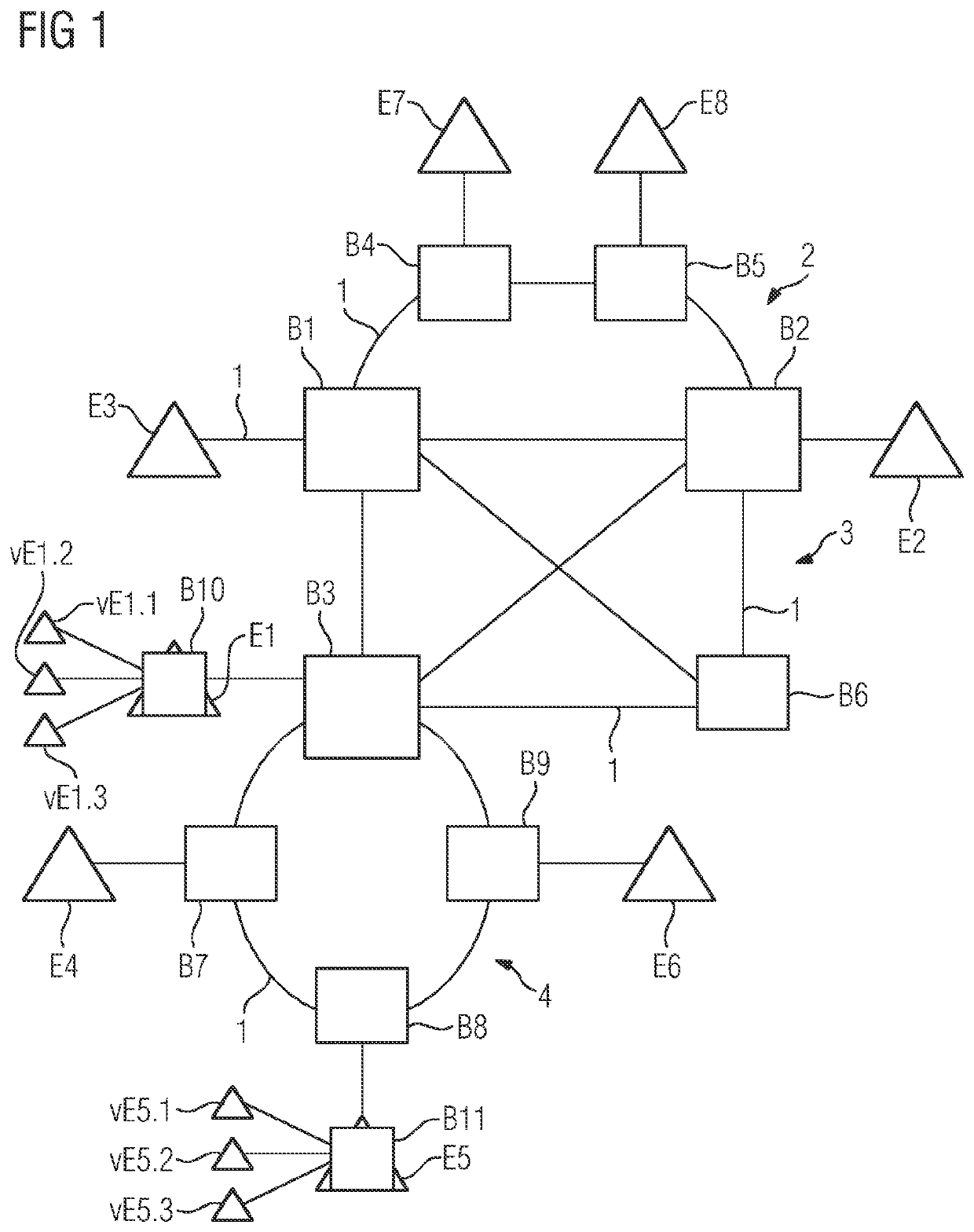
[0074]In a purely schematic illustration, FIG. 1 shows an industrial Ethernet-based network having a plurality of network nodes in the form of bridges B1-B9. The network is a TSN network and all network nodes B1-B9 support TSN standards, in particular the reservation of network resources for real-time data transmission with guaranteed latency.

[0075]The network nodes B1-B9 are connected to one another via cables 1, which can also be referred to as links. Here, the result is three subregions 2, 3, 4 with different network topologies, specifically a first, upper region 2 with a garland-like topology, a second, central region 3 with a meshed topology and a third, lower region 4 with a ring topology.

[0076]The garland topology is suitable, in particular, for cost-sensitive field-level networks or segments for actuators and sensors and is generally redundantly connected to meshed networks, as illustrated by way of example in FIG. 1.

[0077]Meshed networks or segments are suitable, in particu...


PUM


Abstract

A network node, computer program, computer-readable medium and method for fail-safe data transmission in a network, in which data packets are transmitted from a sender to a receiver via redundant paths, upon which resources for the transmission are reserved at participating network nodes utilizing an identifier associated with the relevant path, wherein, if a new path is to be found for at least one of the paths involved, then the previous reservations on all redundant paths are maintained, a new redundant path is determined for the at least one path involved and an attempt is made to reserve resources for the transmission on this new redundant path at the participating network nodes, wherein a new identifier associated with the new path is utilized, and if the new reservations on the at least one new path are successful, then previous reservations on the at least one previous path involved are removed.

Description

CROSS-REFERENCE TO RELATED APPLICATION[0001]This is a U.S. national stage of application No. PCT / EP2019 / 051604 filed 23 Jan. 2019.BACKGROUND OF THE INVENTION1. Field of the Invention[0002]The invention relates to a network node, a computer program, a computer-readable medium and a method for fail-safe data transmission in a network, in particular an industrial network, having a plurality of network nodes.2. Description of the Related Art[0003]In industrial networks, sensor / actuator information is generally interchanged with the controller in a digitized manner via a communication network. A field bus is a bus system that connects field devices, such as measurement sensors (sensors) and actuating elements (actuators), to an automation device for the purpose of communication in an installation. If a plurality of communication participants transmit their messages via the same line, then it is necessary to stipulate who (identifier) says what (measured value, command) when (initiative)....

Claims


Application Information

Patent Timeline
Patent Type & Authority Applications(United States)
IPC IPC(8): H04L12/703H04L12/707H04L12/717H04L12/781G06N7/00
CPCH04L45/28H04L45/22G06N7/005H04L45/52H04L45/42G05B19/0428G05B19/058G05B19/4185G05B19/41845G05B19/0423Y02P90/80G06N7/01
Inventor CHEN, FENGGÖTZ, FRANZ-JOSEFKIESSLING, MARCELNGUYEN, AN NINHSCHMITT, JÜRGEN
Owner SIEMENS AG
Learn More