A slide output module

a slide and output module technology, applied in the field of slide output modules, can solve the problems of limited sample processing time, dehydration of tissue samples on the slides, and potential damage to samples, and achieve the effect of enhancing positional accuracy and being easily accessibl

Pending Publication Date: 2022-02-03
LEICA BIOSYST MELBOURNE
View PDF0 Cites 0 Cited by
  • Summary
  • Abstract
  • Description
  • Claims
  • Application Information

AI Technical Summary

Benefits of technology

This patent is about a slide output tray and cover that are designed to maintain the hydration of a slide with a fluid, such as DI water. The void is bound by a void ceiling in the slide output tray cover, which forms a meniscus to assist in maintaining hydration of the slide. The surface of the void ceiling can have a flat, textured, or ribbed finish to enhance its maintenance of hydration. The slide output tray is provided at a designated angle longitudinally relative to the slide to promote fluid propagation from the fluid inlet to the fluid outlet over the slide in the void. The slide output tray is pivotally connected to the slide output cover, making it easy to access for cleaning. The patent aims to improve the accuracy and reliability of the automated treatment apparatus.

Problems solved by technology

During this time, tissues samples on the slides may start to dehydrate and potentially be damaged.
Increased throughput of samples on slides through the automated staining apparatus is desirable but can also be problematic with a myriad of moving parts requiring calibration, maintenance and cleaning.
In many cases, processed sample throughput is limited by batch processing regimes where sample processing times are limited by the slowest staining protocol (or treatment time) being administered in the batch in the slide treatment modules of the apparatus.

Method used


Image

  • A slide output module
  • A slide output module
  • A slide output module

Examples


Embodiment Construction

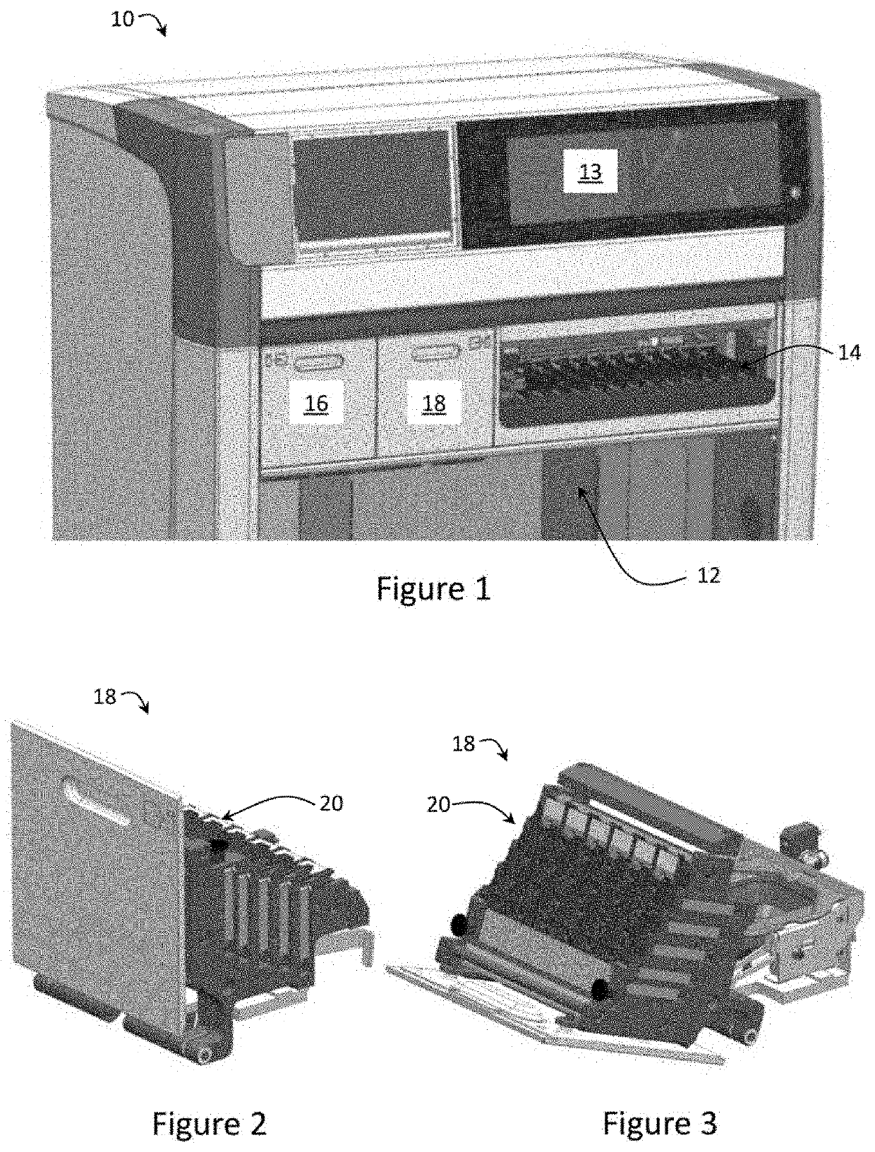
[0033]An automated tissue sample treatment apparatus 10 for treating one or more tissue samples disposed on slides according to an embodiment of the present invention is shown in FIG. 1. In the embodiment, the apparatus 10 comprises a controller (not shown) that is configured to operate the apparatus 10 to automatically treat tissue samples on the slides. However, it will be appreciated by a person skilled in the art that in other embodiments the controller can be implemented remotely from the apparatus 10.

[0034]The apparatus 10 comprises a plurality of slide treatment modules (not shown) located under a housing 13 that are arranged to receive the slides for treatment. The apparatus 10 further comprises at least one bulk fluid robot (BFR), also located under the housing 13, configured by the controller to dispense a plurality of reagents stored in reagent containers 12 to the slides received in the slide treatment modules 12 via an output nozzle disposed on the BFRs to treat tissue ...


PUM

PropertyMeasurementUnit
surface tensionaaaaaaaaaa
angleaaaaaaaaaa
angleaaaaaaaaaa

Abstract

A slide output module for an automated treatment apparatus for treating tissue samples disposed on slides, the slide output module comprising: a slide output tray assembly comprising a slide output tray adjacent to a slide output cover forming one or more voids between the slide output tray and the slide output tray cover for receiving slides therein, wherein the slide output tray cover comprises a first side with a fluid inlet in communication one of the voids, and a second side configured to form a hydration chamber with a slide in said one of the voids to maintain hydration of the slide with fluid received from the fluid inlet for a designated time following treatment of the slide by the automated staining apparatus.

Description

TECHNICAL FIELD[0001]The present invention relates to a slide output module for an automated staining apparatus for treating tissue samples disposed on slides. In particular, the present invention relates to forming a hydration chamber with a slide in a void of the slide output module to maintain hydration of the slide in the void with fluid for a designated period of time.BACKGROUND OF INVENTION[0002]Instrumentation for automated treatment of biological samples, such as anatomical pathology samples, is well known. Treatment may comprise staining procedures of the kinds that are typical in immunochemistry, in-situ hybridisation, special staining and cytology. Automation of some staining procedures has increased the speed with which pathology testing can be completed leading to earlier diagnosis and in some cases, intervention. Staining is typically performed on samples placed on microscopy slides to highlight certain histological features in a biological sample and incubation of the...

Claims


Application Information

Patent Timeline
Patent Type & Authority Applications(United States)
IPC IPC(8): G01N35/00G01N1/31B01L9/00
CPCG01N35/00029G01N1/312G01N2035/0498G01N2035/00079G01N2035/00138B01L9/523B01L2300/0822G01N35/0099B01L2200/142B01L9/52B01L2300/043B01L2200/087G01N35/04
Inventor BOYES, GREGORY WILLIAMGUIRALDENQ, NICOLASAU, BRENDEN ANTHONY
Owner LEICA BIOSYST MELBOURNE
Why Eureka
Try Eureka