
Rotary lobe pump with internal bearing

a rotary lobe pump and internal bearing technology, which is applied in the direction of pump components, engine components, liquid fuel engines, etc., can solve the problems of shortening the service life of the rotary lobe pump, and affecting the service life of the pump

Pending Publication Date: 2022-01-27
VOGELSANG GMBH & CO KG
View PDF8 Cites 1 Cited by
  • Summary
  • Abstract
  • Description
  • Claims
  • Application Information

AI Technical Summary

Benefits of technology

The invention is a pump that uses a fixed axle body connected to the pump housing through a screw or force closure. This design allows for easier centering and alignment of the axle body, and may also enable replacement of the axle body. Bearings are preferably mounted inside the rotary piston for rotatable mounting. The first and second drive devices are preferably arranged on opposite sides of the pump housing, which makes it easier to use larger drives. The technical effect of this design is a more reliable and efficient pump with improved performance and reliability.

Problems solved by technology

A fundamental problem that arises with such rotary lobe pumps is due to the fact that the replacement of wearing parts is associated with a relatively high effort, which has a negative effect on the maintenance costs and can also lead to longer downtimes of the rotary lobe pumps.
However, with this design, the executable length of the rotary piston is severely limited, since the drive shaft, which is connected to the rotary piston, is only mounted on one side of the rotary piston and therefore cannot be of any length.
However, a disadvantage of such a rotary lobe pump is that wearing parts, such as the bearings and seals, cannot be replaced as easily as the rotary pistons.
Another general problem is that such pumps have a relatively high weight and are relatively large due to their design, which is negative in particular for the mobile use of such pumps, for example when used in or on vehicles.

Method used


Image

  • Rotary lobe pump with internal bearing
  • Rotary lobe pump with internal bearing
  • Rotary lobe pump with internal bearing

Examples


Embodiment Construction

[0057]In the figures, identical or essentially functionally identical or similar elements are designated with the same reference signs.

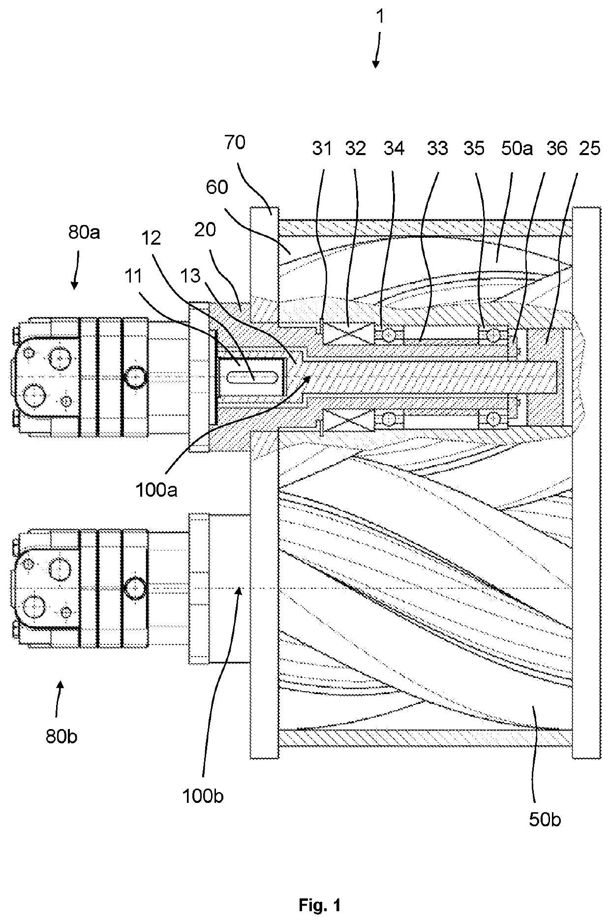
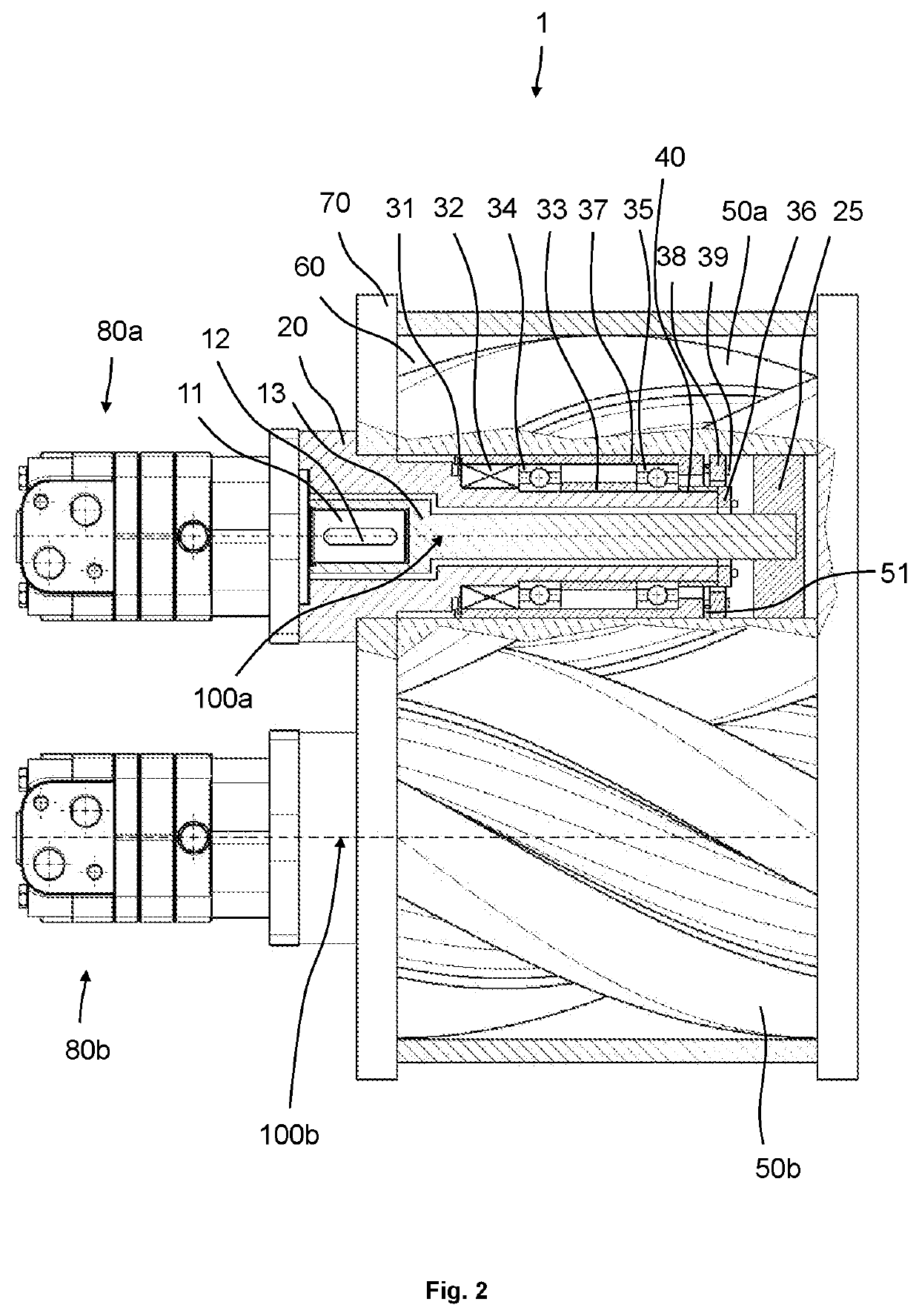
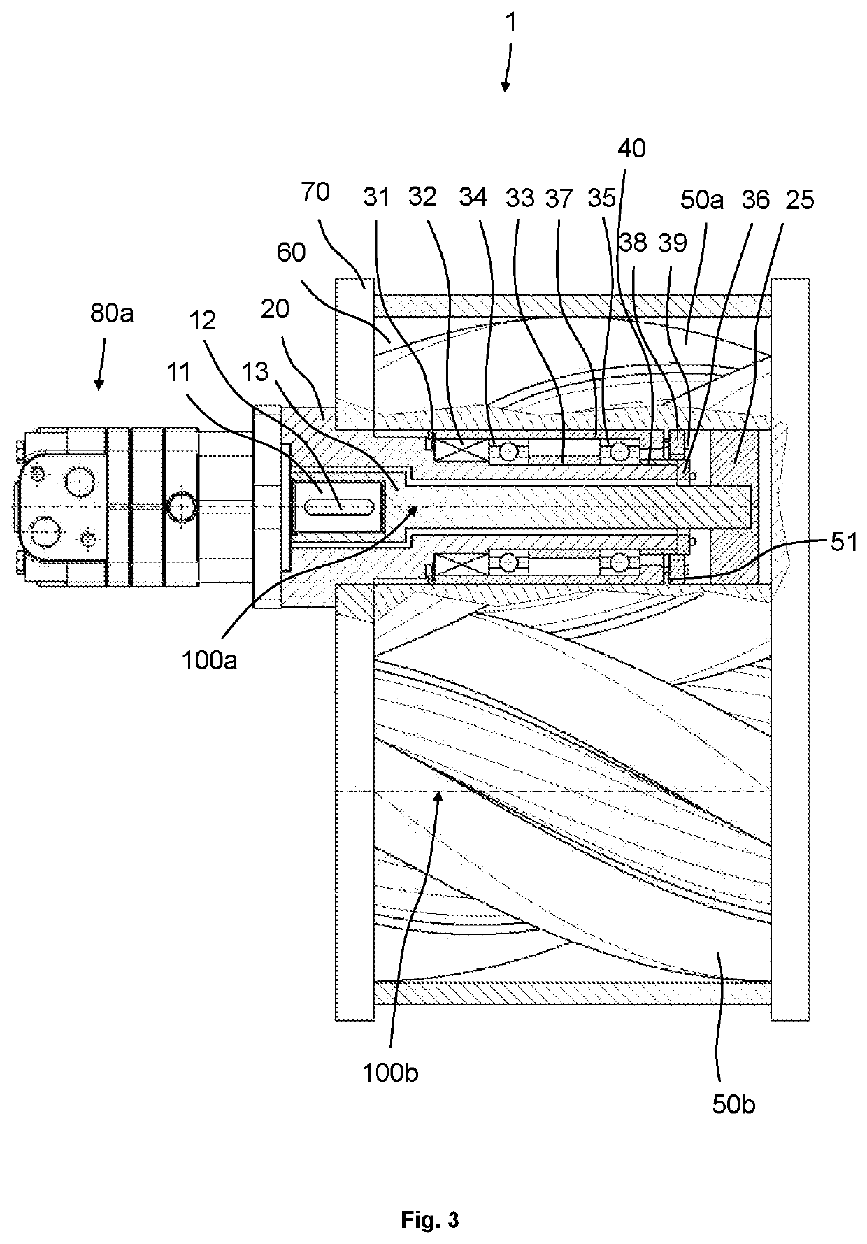
[0058]FIG. 1 shows a rotary lobe pump 1 comprising a pump housing 70, wherein the pump housing 70 encloses the pump room 60. Two drive devices 80a, 80b are arranged on one side of the pump housing. The first drive device 80a is connected to the first fixed axle body 20. The fixed axle body 20 is connected to the pump housing 70. The drive device 80a has a shaft 11, which is connected by means of a shaft-hub connection 12 to the drive shaft 13, which extends through the fixed axle body 20 along the first axis of rotation 100a. The drive shaft 13 is thereby connected to the first rotary piston 50a by means of a shaft-hub connection 25 and thus transmits a torque from the first drive device 80a to the first rotary piston 50a. The second rotary piston 50b is similarly driven by the second drive device 80b, which drives a second drive shaft (not shown) th...


PUM


Abstract

A rotary lobe pump having a pump housing with a pump room, an inlet opening and an outlet opening, a first multi-lobe rotary piston, which is arranged in the pump room and is rotatably mounted about a first axis of rotation, a second multi-lobe rotary piston, which is arranged in the pump room and is rotatably mounted about a second axis of rotation spaced apart from the first axis of rotation and meshingly engages in the first rotary piston, wherein the first and second rotary pistons are drivable in opposite directions and are designed to generate a flow of a conveyed medium from the inlet opening through the pump room to the outlet opening by counter-rotation about the first and second axis of rotation, respectively, and a drive device, which is mechanically coupled to the rotary pistons for driving the rotary pistons.

Description

CROSS-REFERENCE TO FOREIGN PRIORITY APPLICATION[0001]The present application claims the benefit under 35 U.S.C. §§ 119(b), 119(e), 120, and / or 365(c) of PCT / EP2019 / 085094 filed Dec. 13, 2019, which claims priority to German Application No. 20 2018 107 141.6 filed Dec. 13, 2018.FIELD OF THE INVENTION[0002]The invention relates to a rotary lobe pump for conveying a particle-laden conveyed medium, comprising a pump housing with a pump room, an inlet opening and an outlet opening, a first multi-lobe rotary piston, which is arranged in the pump room and is rotatably mounted about a first axis of rotation, a second multi-lobe rotary piston, which is arranged in the pump room and is rotatably mounted about a second axis of rotation spaced apart from the first axis of rotation and meshingly engages in the first rotary piston, wherein the first and second rotary pistons are drivable in opposite directions and are designed to generate a flow of the conveyed medium from the inlet opening throu...

Claims


Application Information

Patent Timeline
Patent Type & Authority Applications(United States)
IPC IPC(8): F04C2/12F04C15/00F04C2/08
CPCF04C2/126F04C15/0061F04C2/084F04C2240/805F04C15/0038F04C2240/52F04C2240/20F04C15/008F04C2/16F04C2240/50F04C2240/402F04C15/0034F04C13/001F04C2240/30F05B2240/50
Inventor KRAMPE, PAULAHRENS, HENRIK
Owner VOGELSANG GMBH & CO KG
Learn More