Optical scanning apparatus and image forming apparatus

a technology of optical scanning and image forming, which is applied in the direction of polarising elements, instruments, visual presentations, etc., can solve the problems of increasing the thickness of the optical scanning apparatus, difficulty in ensuring a vignetting margin, so as to achieve the effect of minimizing the bow

Pending Publication Date: 2022-01-20
SHARP KK
View PDF0 Cites 0 Cited by
  • Summary
  • Abstract
  • Description
  • Claims
  • Application Information

AI Technical Summary

Benefits of technology

[0022]The optical scanning apparatus and the image forming apparatus according to the present invention produce an advantageous effect such that it is possible to cause the beam light to squarely enter the deflection mirror, ensure a vignetting margin, and minimize a bow due to the optical functions of the first polarizing member and the second polarizing member.

Problems solved by technology

In the light ray layout where the beam light enters the deflection mirror obliquely from the side, however, the effective area of the reflection surface is narrow at a certain angle of the deflection mirror, which causes difficulty in ensuring a vignetting margin.
In particular, when a MEMS mirror is used as a deflection mirror, there is the issue of the difficulty in ensuring a vignetting margin due to the small mirror size in the main scanning direction as compared to a polygon mirror.
In the light ray layout in which the beam light enters at an angle with respect to the rotation axis of the deflection mirror, however, the optical path of the beam light also extends in the direction of the rotation axis of the deflection mirror, which causes the issue of an increase in the thickness of the optical scanning apparatus.
Furthermore, as the reflection position of the beam light is different between the image height center and the scanning end, there is also the issue of the occurrence of a sub-scanning line bow of a reflected light ray.
In this light ray layout, however, a deflection mirror (here, a polygon mirror) needs to reflect the beam light twice on one reflection surface, and the distance between the two reflection points becomes long in the main scanning direction at a certain angle of the deflection mirror, which causes the issue of an increase in the size of the deflection mirror as compared to the conventional one rather than ensuring a vignetting margin.

Method used


Image

  • Optical scanning apparatus and image forming apparatus
  • Optical scanning apparatus and image forming apparatus
  • Optical scanning apparatus and image forming apparatus

Examples


first embodiment

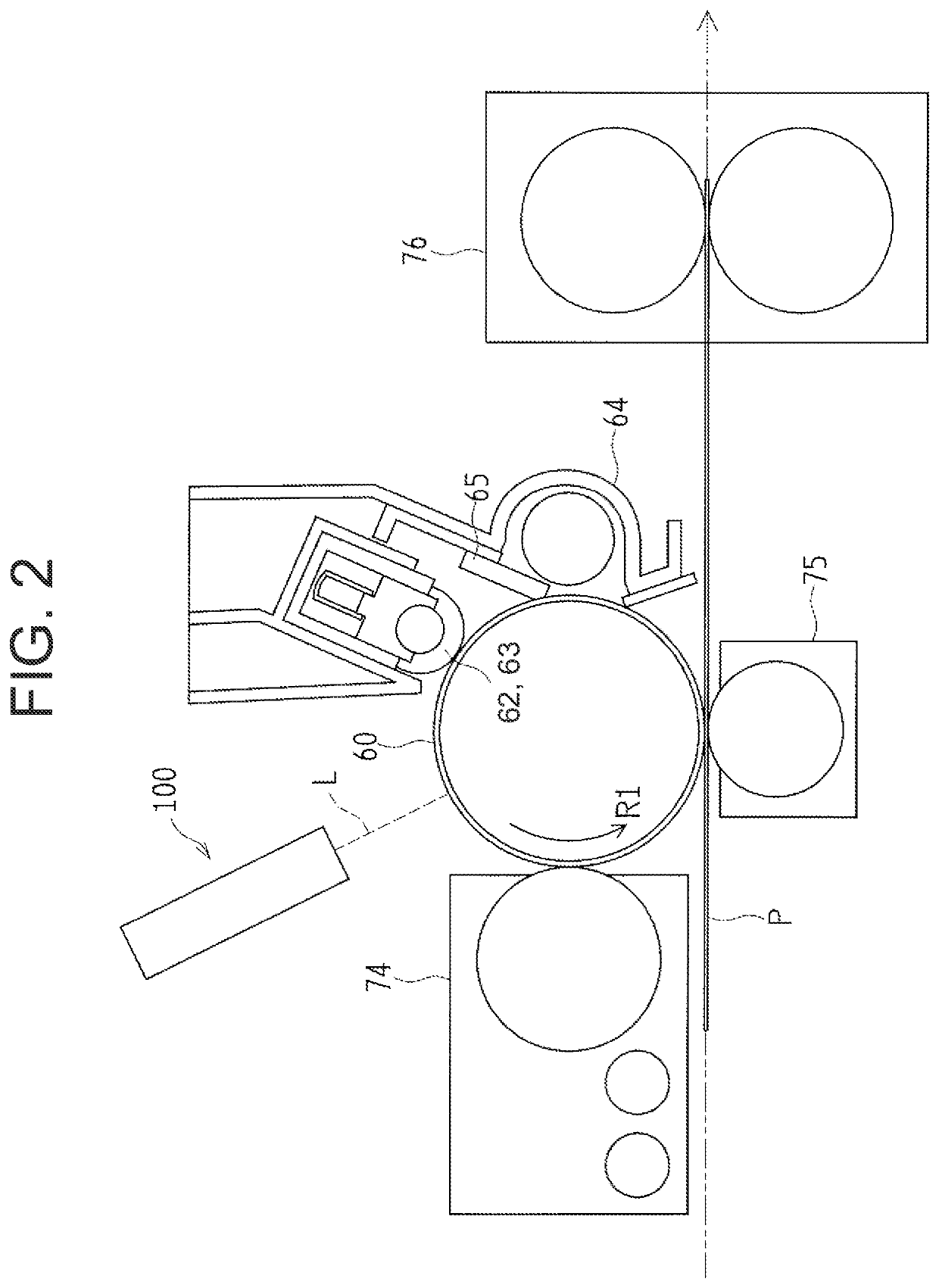
[0032]An embodiment of the present invention will be described below in detail with reference to the drawings. FIG. 1 is a vertical cross-sectional view schematically illustrating an overall configuration of an image forming apparatus 200 to which an optical scanning apparatus 100 according to the present embodiment is applied. The image forming apparatus 200 illustrated in FIG. 1 is a digital multifunction peripheral capable of printing a document read by a scanner 81 or printing image data input from an external machine via a network.

[0033]The image forming apparatus 200 includes a photoconductor drum 60, a charging unit 62, a cleaning unit 64, the optical scanning apparatus 100, a developing unit 74, a transfer unit 75, a fixing unit 76, the scanner 81, a paper feed tray 82, and a paper discharge tray 83.

[0034]The scanner 81 includes a document set tray, an automatic document feeder, a document read device, and the like. The document read device includes a document placement tabl...

second embodiment

[0063]In the configuration illustrated according to the first embodiment, the MEMS mirror 23 is used as the deflection mirror of the optical scanning apparatus 100. However, the present invention is not limited thereto, and a polygon mirror may be used as the deflection mirror. FIG. 6 is a side view schematically illustrating an optical system of an optical scanning apparatus 100A according to a second embodiment.

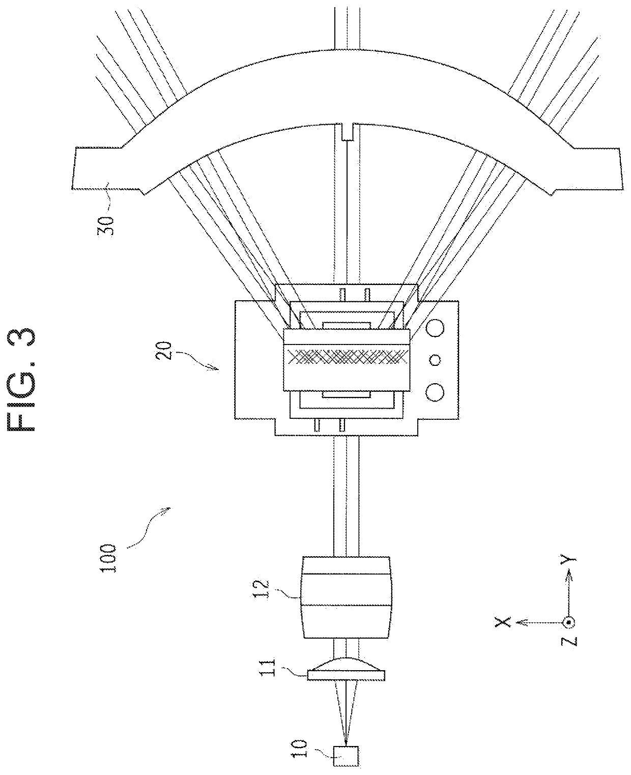
[0064]The optical scanning apparatus 100A illustrated in FIG. 6 has a configuration including a beam deflector 20A instead of the beam deflector 20 in the optical scanning apparatus 100 of FIG. 3. The beam deflector 20A includes a polygon mirror 25 as a deflection mirror instead of the MEMS mirror 23 of FIG. 3. In the optical scanning apparatus 100A, the rotation axis of the polygon mirror 25 is arranged in a direction (i.e., the Y-axis direction) parallel to the optical axis of the beam light L immediately before being reflected by the first polarizing member 21 as is the ...

third embodiment

[0065]In the optical scanning apparatus 100 of FIG. 3, the beam light L emitted from the light source 10 includes the s-polarization component and the p-polarization component, only the s-polarization component reflected by the first polarizing member 21 is used as a scanning light for the scanned object, and the p-polarization component passed through the first polarizing member 21 is not used as a scanning light. For this reason, it is necessary to prevent the p-polarization component having passed through the first polarizing member 21 from passing through the emission optical system and being emitted from the optical scanning apparatus 100.

[0066]FIG. 7 is a side view schematically illustrating an optical system of an optical scanning apparatus 100B according to a third embodiment. The optical scanning apparatus 100B illustrated in FIG. 7 has a configuration substantially similar to that of the optical scanning apparatus 100 of FIG. 3 but includes a light shield 40 that blocks th...


PUM

PropertyMeasurementUnit
angleaaaaaaaaaa
optical scanningaaaaaaaaaa
phase differenceaaaaaaaaaa

Abstract

An optical scanning apparatus includes a first polarizing member and a second polarizing member between a light source and a MEMS mirror that is a deflection mirror. The first polarizing member reflects a first polarization component included in a beam light emitted from the light source so as to squarely enter the MEMS mirror and passes a second polarization component having a phase difference of a half-wavelength with respect to the first polarization component. The second polarizing member is provided between the first polarizing member and the MEMS mirror to pass the first polarization component reflected by the first polarizing member therethrough twice before and after being reflected by the MEMS mirror to change the first polarization component into the second polarization component. A rotation axis of the MEMS mirror is parallel to an optical axis of the beam light immediately before being reflected by the first polarizing member.

Description

BACKGROUND OF THE INVENTIONField of the Invention[0001]The present invention relates to an optical scanning apparatus and an image forming apparatus including the optical scanning apparatus.Description of the Background Art[0002]There are conventionally known optical scanning apparatuses that include an optical system including a light source and a deflection mirror such as a polygon mirror or a micro-electro-mechanical systems (MEMS) mirror to reflect a beam light from the light source by the deflection mirror and scan a scanned object.[0003]In order to prevent interference with emitted light rays after being reflected by the deflection mirror, the optical scanning apparatus often adopts a light ray layout in which a beam light enters the deflection mirror not squarely but obliquely from the side.[0004]Furthermore, in order to prevent the beam light from falling outside the deflection mirror, the optical scanning apparatus needs to ensure a vignetting margin that allows for an erro...

Claims


Application Information

Patent Timeline
Patent Type & Authority Applications(United States)
IPC IPC(8): G02B26/08G02B26/10G02B27/28G02B5/30
CPCG02B26/0833G02B5/3083G02B27/283G02B26/10G02B26/124B41J2/471G06K15/1204
Inventor YAMAMOTO, HIROSHISATO, HIDENORIMOTOYAMA, TAKAHARU
Owner SHARP KK
Why Eureka
Try Eureka