
Method for setting a throttle valve, engine control unit, and a vehicle

a technology of throttle valve and control unit, which is applied in the direction of electric control, combustion engines, machines/engines, etc., can solve the problems of increasing the size of the mass flow through the throttle valve, entail certain difficulties, and the resultant pressure changes in the intake manifold, so as to achieve accurate steady-state closed-loop control

Active Publication Date: 2022-01-20
VOLKSWAGEN AG
View PDF1 Cites 1 Cited by
  • Summary
  • Abstract
  • Description
  • Claims
  • Application Information

AI Technical Summary

Benefits of technology

The invention aims to improve the control of engine intake manifold pressure and the amount of fresh air charge in the cylinder. This is achieved through a steady-state closed-loop control of the throttle valve. The technical effect of this invention is to enhance engine performance by optimizing air intake and combustion efficiency.

Problems solved by technology

The closed-loop control of the intake manifold pressure in the region of pressure equalization—approximately equal pressure before and after the throttle valve—at the throttle valve (“overtravel of the throttle valve”) entails certain difficulties.
Thus, for instance, the response of the intake manifold pressure (pressure downstream of the throttle valve—after the throttle valve) in the region of pressure equalization is increasingly insensitive to throttle valve movements, which has the result that, as the opening angle of the throttle valve increases, the resultant pressure changes in the intake manifold and the accompanying changes in the mass flow through the throttle valve likewise become ever smaller.

Method used


Image

  • Method for setting a throttle valve, engine control unit, and a vehicle
  • Method for setting a throttle valve, engine control unit, and a vehicle
  • Method for setting a throttle valve, engine control unit, and a vehicle

Examples


Embodiment Construction

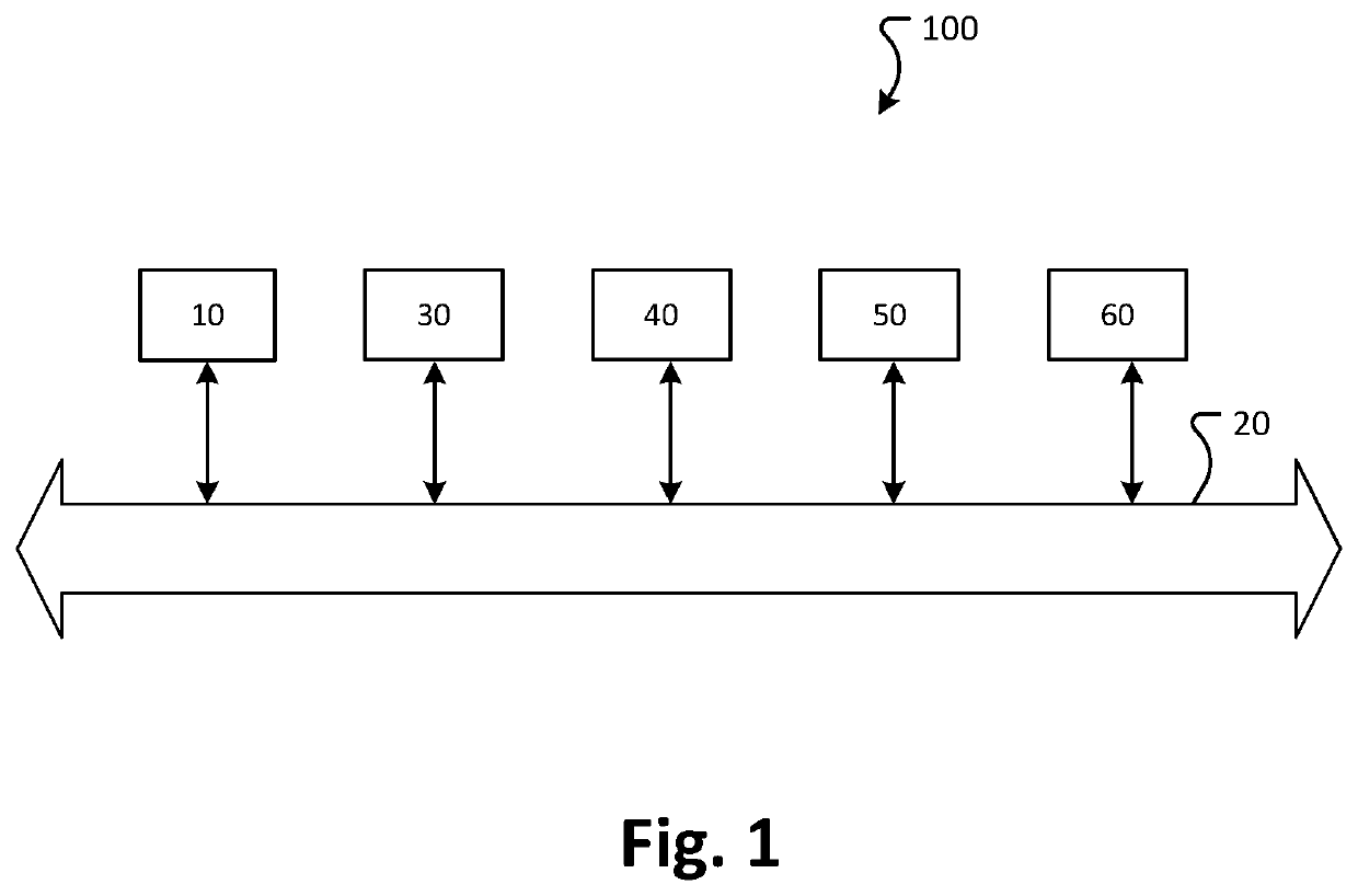
[0050]FIG. 1 shows a block diagram that schematically represents the configuration of a vehicle according to an exemplary embodiment of the present invention.

[0051]The vehicle 100 includes multiple components that communicate with one another over a data bus 20, namely an engine control unit 10, a throttle control unit 30, an exhaust turbocharger control unit 40, a transmission control unit 50, and a clutch control unit 60. The vehicle 100 can be driven by an internal combustion engine, wherein the internal combustion engine is a multicylinder spark ignition engine.

[0052]An engine control unit (ECU) 10 is an electronic control unit that controls a number of actuators of the internal combustion engine in order to ensure optimal engine performance. For example, the engine control unit (ECU) 10 can control the position of a throttle valve and / or the operation of an exhaust turbocharger. The control of the throttle valve and / or of the exhaust turbocharger can be based on a continuous cl...


PUM


Abstract

A method for setting a throttle valve that includes feedback control of a throttle position of the throttle valve in the entire operating range of an internal combustion engine, wherein the feedback control is based on an internal model control principle.

Description

[0001]This nonprovisional application claims priority under 35 U.S.C. § 119(a) to German Patent Application No. 10 2020 208 865.9, which was filed in Germany on Jul. 16, 2020, and which is herein incorporated by reference.BACKGROUND OF THE INVENTIONField of the Invention[0002]The present invention relates to a closed-loop control of the intake manifold pressure close to pressure equalization at the throttle valve.Description of the Background Art[0003]Internal combustion engines convert chemical energy into mechanical energy. For this purpose, a flammable mixture of fuel and air is introduced into a combustion chamber, where it is ignited. The torque delivered by the internal combustion engine is set by throttling the quantity of air in the mixture with a throttle valve. A throttle valve is the component of the internal combustion engine with which the torque created by the throttling of the flow rate is set (quantity control). It is located in the intake tract between the air filte...

Claims


Application Information

Patent Timeline
IPC IPC(8): F02D41/00F02B37/24
CPCF02D41/0002F02D2200/0414F02D2200/0406F02B37/24F02D41/18F02D41/02F02D2200/04F02D2200/0404F02D41/1401F02D2041/1433F02D2200/0408F02D11/105F02D2200/0402Y02T10/40Y02T10/12
Inventor GARWON, MAIKOBASS, KOSTYANTYN
Owner VOLKSWAGEN AG
Learn More