
Hanging device

a self-clamping and hanging device technology, applied in the direction of machine supports, instruments, music aids, etc., can solve the problems of hard to hold their belongings in a place, such as purses, handbags, totes, etc., and achieve the effect of increasing the friction for

Pending Publication Date: 2021-12-30
THORNTON BRANDON
View PDF0 Cites 0 Cited by
  • Summary
  • Abstract
  • Description
  • Claims
  • Application Information

AI Technical Summary

Benefits of technology

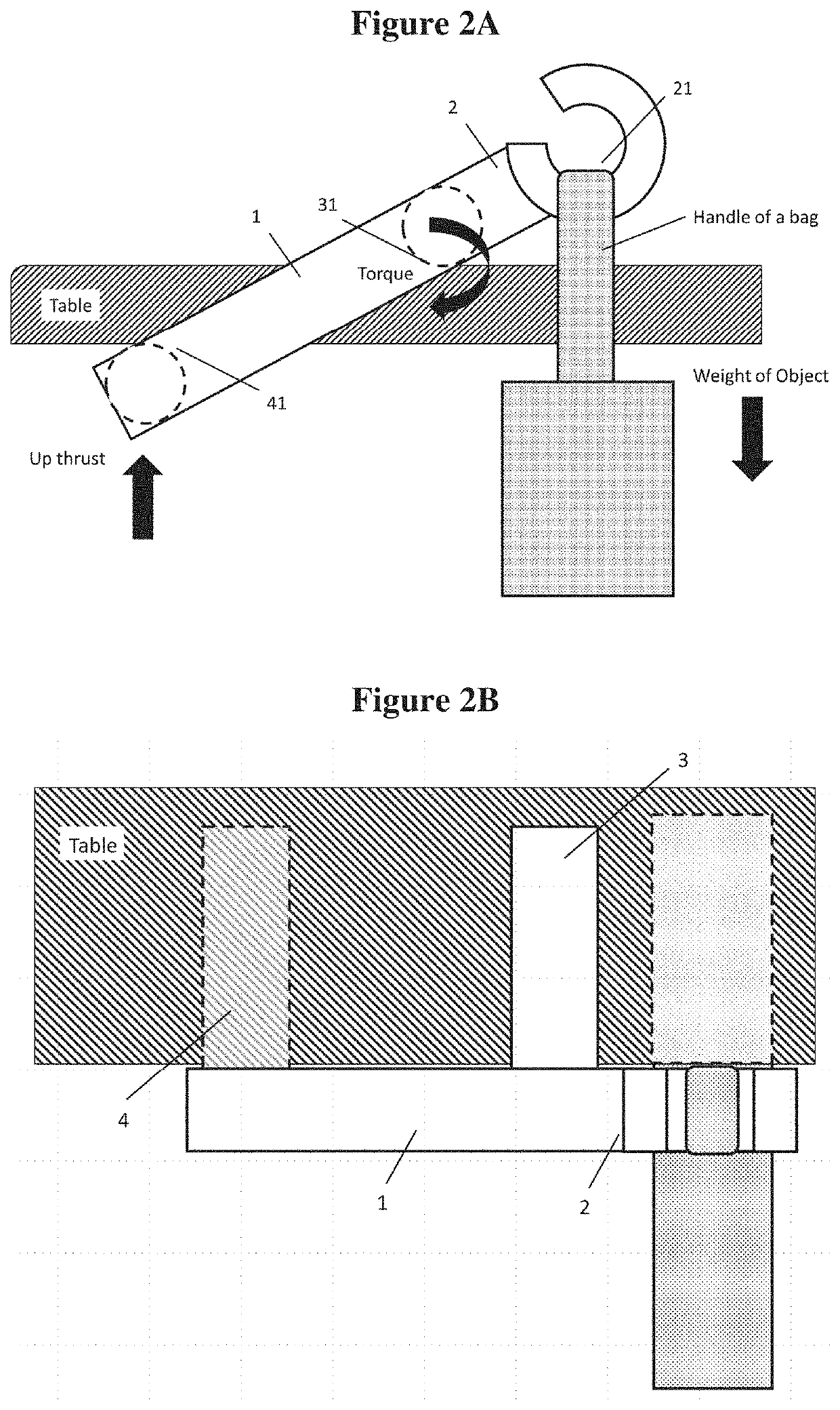
The present invention allows for a device to hold itself in position using a pivot point and clamping arm. The device can be held by the force of gravity or other objects hanging from it. The pivot point, clamping point, and holding point are on the same or different vertical planes. The weight of the device and objects adds force to the surface of the supporting element through the pivot point and clamping point. This holds the device in place. The friction force between the pivot point, clamping point, and the supporting element stops the device from moving. The pivot arm and clamping arm increase the friction force by creating more contact area.

Problems solved by technology

When people are in some public spaces like restaurants, cafés, bars or libraries, they usually find it is hard to a place to hold their belongings like purses, handbags, totes, backpacks, shopping bags and instruments in a secure way that will not restrict their movement or contaminate their luggage.

Method used


Image

  • Hanging device
  • Hanging device
  • Hanging device

Examples


example 1

[0114]In one embodiment, this invention provides a device with a self-clamping mechanism for hanging objects from a supporting element. In another embodiment, the device comprises a body (1), a holding arm (2), a pivot arm (3) and a clamping arm (4) as shown in FIG. 1A. When the pivot arm is placed onto a supporting element such as a table, the point of contact between the pivot arm and the supporting element will form a pivot point (31) such that a load placed onto a holding point (21) at the holding arm (2) will create a torque to thrust the clamping arm (4) onto the bottom side of the table at the clamping point (41). In this way, the force balance will lock the device in place so that it will not fall off easily. In one embodiment, there is a horizontal distance, between the holding point and pivot point which can act as a lever arm for creating a torque.

[0115]By careful design of the holding arm (2), pivot arm (3) and clamping arm (4), the plane of rotation can be manipulated. ...

example 2

[0123]The portable self-clamping device is fabricated by the following steps:[0124]1. Designing the device of this invention using a software e.g. Ultimaker Cura.[0125]2. 3D-printing the device via a 3D Printer, e.g. Monoprice® Maker Select, by using filaments of Acrylonitrile Butadiene Styrene (ABS), thereby obtaining the device.

example 3

[0126]According to one embodiment of the present invention, the 3D-printed device is used in the following procedures:[0127]1. Obtaining the device according to the preparation method Example 1;[0128]2. Attaching the pivot arm of the device to the top surface of a table, creating a pivot point wherein a torque generated about the pivot point by the device's weight thrusts the end of the clamping arm against the bottom side of the table, creating a clamping point, wherein the device is secured to the table with the help of its own weight;[0129]3. After the device is clamped to the table, hanging a handbag to the holding arm generates additional torque about the pivot point to thrust the end of the clamping arm with more force, further securing the device to the table;[0130]4. When needed, taking the handbag off the holding arm; and[0131]5. Removing the device from the table.


PUM


Abstract

This invention provides a self-clamping device for hanging objects from a supporting element. In one embodiment, the device has a body, a holding arm, a pivot arm and a clamping arm, the pivot arm and the clamping arm are affixed to the body, the holding arm projects from the body forming a holding point between the holding arm and the body for hanging objects; and the pivot arm is configured to contact a top side of the supporting element, forming a pivot point; an object hanging from the holding point generates a torque about the pivot point to thrust the end of the clamping arm against a bottom side of the supporting element forming a clamping point.

Description

CROSS-REFERENCE TO RELATED APPLICATIONS[0001]This application claims the benefit of U.S. Provisional Application No. 62 / 815,176, filed Mar. 7, 2019. The entire contents and disclosures of the preceding application are incorporated by reference into this application.[0002]Throughout this application, various references are referred to and disclosures of these publications in their entireties are hereby incorporated by reference into this application to more fully describe the state of the art to which this invention pertains.FIELD OF THE INVENTION[0003]The present invention relates to a portable self-clamping device for hanging objects, such as bags, purses, handbags, totes, backpacks and shopping bags from surface of tables, desks, shelves, cupboards or other supporting elements. The application cites various publications, the entire contents of which are incorporated herein by reference into this application.BACKGROUND OF THE INVENTION[0004]When people are in some public spaces lik...

Claims


Application Information

Patent Timeline
Patent Type & Authority Applications(United States)
IPC IPC(8): F16M13/02F16B2/00A47G29/08
CPCF16M13/022G10G5/00A47G29/083F16B2/005
Inventor THORNTON, BRANDON
Owner THORNTON BRANDON
Learn More