Circuit system and circuit control method applied to motor drive

a circuit control and circuit technology, applied in the control system, dynamo-electric converter control, dc-dc conversion, etc., can solve the problems of shortening affecting the service life of the load, and achieve the effect of stable rotation speed and torque of the motor, stable output voltage, and low cost of the control system

Active Publication Date: 2021-12-23
NAT CHENG KUNG UNIV
View PDF0 Cites 0 Cited by
  • Summary
  • Abstract
  • Description
  • Claims
  • Application Information

AI Technical Summary

Benefits of technology

This patent describes a technical solution that reduces the voltage ripple and operation loss of a drive circuit, improves the stability of the output voltage, reduces the required DC capacitance and the overall volume of the circuit, and improves the performance of the motor. This is achieved through a phase-locked circuit that reduces the load current and DC voltage ripple, which leads to lower costs and increased stability of the control system.

Problems solved by technology

However, in the start-up process or the switching process, inrush current surges, ripples, etc. are often generated, shortening the service life of the load.
However, the aforementioned patent cannot reduce the ripple effectively, and may affect the service life of the load.

Method used


Image

  • Circuit system and circuit control method applied to motor drive
  • Circuit system and circuit control method applied to motor drive
  • Circuit system and circuit control method applied to motor drive

Examples


Embodiment Construction

[0025]Embodiments of the present invention will now be described, by way of example only, with reference to the accompanying drawings.

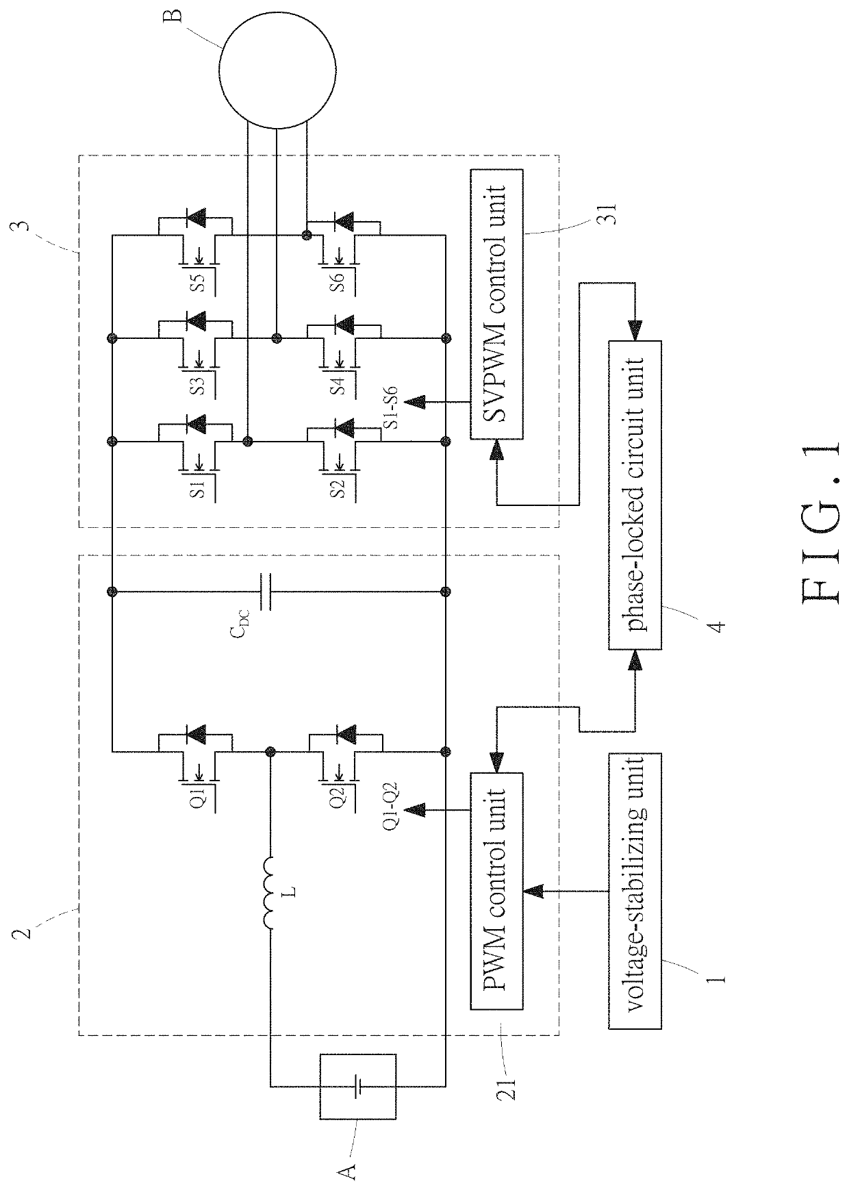
[0026]Referring to FIG. 1, a circuit system applied to a motor drive according to an embodiment of the present invention, comprising a voltage-stabilizing unit 1, a DC power conversion unit 2, an inverter unit 3 and a phase-locked circuit unit 4 for performing a circuit control method applied to a motor drive.

[0027]The DC power conversion unit 2 is a DC-to-DC power converter. The DC power conversion unit 2 includes an inductor L, two power transistors, at least one DC capacitor CDC, and a PWM control unit 21. Although only one DC capacitor is shown in FIG. 1, multiple DC capacitors are usually required in practice; the present invention has no limitation on the number of the DC capacitor. The two power transistors serve as a first switch Q1 and a second switch Q2, respectively.

[0028]The inverter unit 3 includes a plurality of power transistors and an ...


PUM


Abstract

A circuit system and a circuit control method applied to a motor drive are disclosed. The circuit control method includes the steps of providing a phase-locked circuit unit and providing a PWM control unit. The phase-locked circuit unit enables a first carrier signal and a second carrier signal to have identical amplitudes and starting points. The PWM control unit compares the first carrier signal with a reference signal for controlling a switch. When a load current is independently supplied by at least one DC capacitor, a SVPWM control unit controls an inverter unit for the load current to be zero, thereby reducing DC voltage ripple, operation loss and transient voltage surge.

Description

FIELD OF THE INVENTION[0001]The present invention relates to a circuit system and a circuit control method, and more particularly to a circuit system and a circuit control method applied to a motor drive.BACKGROUND OF THE INVENTION[0002]In these days, people pay more attention to environmental issues such as the global greenhouse effect, energy saving and carbon reduction. All countries are implementing reductions in the use of fossil fuels. In the developments of various vehicles, the use of electric motors to replace traditional fuel engines has become a common and clear trend. According to the research conducted by the International Energy Agency, there will be large rechargeable electric vehicles on the market throughout the world in the next 30 years. For example, the unmanned vehicle system used in the intelligent production system can offset the operating energy of about three transport operators and one traditional transport vehicle from the perspective of economic benefits....

Claims


Application Information

Patent Timeline
Patent Type & Authority Applications(United States)
IPC IPC(8): H02P27/08
CPCH02P27/085H02P2201/09H02M1/15H02M1/007H02M7/5395H02M3/158
Inventor TSAI, MI-CHINGPAI, FU-SHENGHSIEH, MIN-FUSHIH, KAI-JUNGWU, ZHENG-XUAN
Owner NAT CHENG KUNG UNIV
Why Eureka
Try Eureka