
Hydraulic lifting device for a chassis of a mobile device, chassis and mobile device

a mobile device and hydraulic lifting technology, applied in the field of hydraulic lifting devices for mobile devices, can solve the problems of creeping pressure loss, unobservable increase in the installation space of the valve block, etc., and achieve the effect of effectively preventing unintentional lowering over tim

Pending Publication Date: 2021-12-23
HAWE HYDRAULIK SE
View PDF0 Cites 0 Cited by
  • Summary
  • Abstract
  • Description
  • Claims
  • Application Information

AI Technical Summary

Benefits of technology

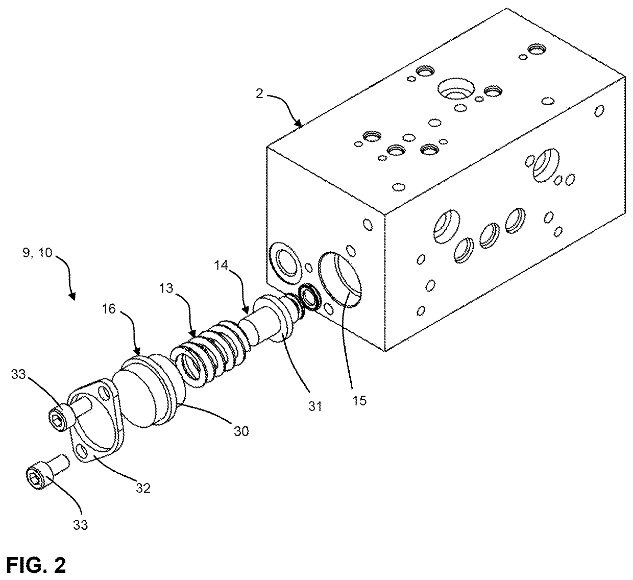
The present invention provides a hydraulic lifting device for a mobile device that prevents unintentional lowering over time without increasing the size of the valve block. This is achieved by integrating a pressure accumulator into the valve block, which compensates for pressure losses and prevents the retraction of the second cylinder device. The pressure accumulator can also be used to compensate for pressure losses caused by a micro-leakage or a creeping pressure loss. The valve block has two identical pressure accumulators disposed upstream of the respective secondary non-return valves to prevent a retracting at both secondary cylinders due to a pressure loss at the respective secondary non-return valve. The pressure accumulator has a spring and a piston, which allows for a compact design that can be easily integrated into the valve block. The pressure accumulator has a sealing cap that reduces installation space of the valve block.

Problems solved by technology

Furthermore, such a pressure accumulator can also be easily integrated into the valve block, so that the overall installation space of the valve block is not noticeably increased.
It is also conceivable that a micro-leakage at the drainage device leads to a creeping pressure loss.

Method used


Image

  • Hydraulic lifting device for a chassis of a mobile device, chassis and mobile device
  • Hydraulic lifting device for a chassis of a mobile device, chassis and mobile device
  • Hydraulic lifting device for a chassis of a mobile device, chassis and mobile device

Examples


Embodiment Construction

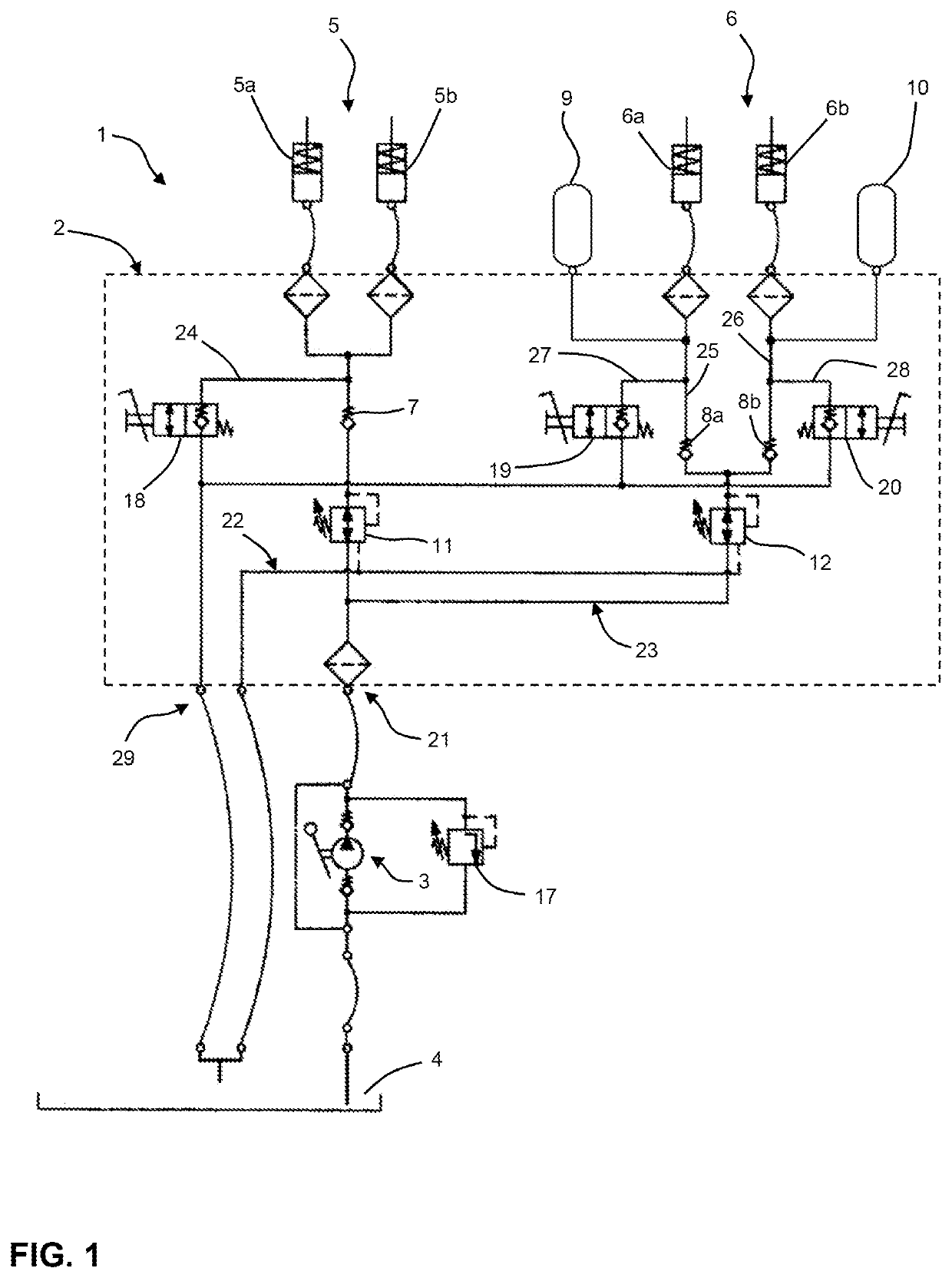
[0024]FIG. 1 shows a hydraulic circuit diagram of a hydraulic lifting device 1 according to the invention for a mobile medical device, for example a surgical robot. The hydraulic lifting device 1 has a valve block 2, a manually operated pump 3, a tank 4, a first cylinder device 5 and a second cylinder device 6. The valve block 2 comprises a first and a second pressure accumulator 9, 10. The first cylinder device 5 comprises two primary cylinders 5a, 5b and the second cylinder device 6 comprises two secondary cylinders 6a, 6b. In the embodiment shown, the primary cylinders 5a, 5b and the secondary cylinders 6a, 6b are configured as single-acting hydraulic cylinders with return springs.

[0025]The pump 3 is connected to the tank 4 and the valve block is connected to the pump 3 via a first connection 21. When the pump 3 is actuated, hydraulic fluid is pumped from the tank 4 via the first connection 21 to the valve block 2. In the valve block 2, a first line arrangement 22 supplies the fi...


PUM


Abstract

A hydraulic lifting device for a chassis of a mobile device has a valve block, a pump, a tank, a first cylinder device and a second cylinder device. The first cylinder device and the second cylinder device can be selectively pressurized by the pump or connected to tank via the valve block. The first cylinder device is connected to the pump via at least one primary non-return valve disposed in the valve block. The second cylinder device is connected to the pump via at least one secondary non-return valve disposed in the valve block. The valve block has at least one pressure accumulator downstream of the at least one secondary non-return valve in the flow direction from the pump to the second cylinder device. Furthermore, a chassis with such a lifting device and to a mobile device with a chassis is provided.

Description

CROSS-REFERENCE TO RELATED APPLICATIONS[0001]This application claims priority to German Application No. 10 2020 207 787.8, filed Jun. 23, 2020, of which is hereby incorporated by reference in its entirety.FIELD OF THE INVENTION[0002]The present invention relates to a hydraulic lifting device for a chassis of a mobile device, a chassis with such a hydraulic lifting device and a mobile device with a chassis according to the invention. The mobile device may in particular be a medical device.BACKGROUND OF THE INVENTION[0003]Such hydraulic lifting devices or chassis are known from the prior art and are used in particular in the medical field for mobile medical equipment, for example in mobile operating robots or mobile operating tables. These hydraulic lifting devices, also known as “floor lock” systems, are used to firmly fix, support and level the mobile medical equipment during use, regardless of the ground.[0004]To make this possible, such hydraulic lifting devices regularly have a v...

Claims


Application Information

Patent Timeline
Patent Type & Authority Applications(United States)
IPC IPC(8): B66F3/30B66F3/46
CPCB66F3/30B66F3/46F15B11/16F15B1/02F15B13/02F15B20/005F15B2211/865F15B2211/71F15B2211/212F15B1/04F15B2201/21F15B2201/31F15B2201/405F15B2201/605F15B13/0814F15B2211/30515F15B2211/41581F15B2211/50554F15B2211/5158F15B2211/5157A61G7/0528F15B11/10F15B2211/20507F15B2211/30505F15B11/003F15B2211/423F15B2211/50518F15B2211/7052A61G13/104
Inventor MÜLLER, SVEN
Owner HAWE HYDRAULIK SE
Learn More