
Distributed automated synthesis of correct-by-construction controllers

Pending Publication Date: 2021-12-16
TECH UNIV MUNCHEN
View PDF4 Cites 0 Cited by
  • Summary
  • Abstract
  • Description
  • Claims
  • Application Information

AI Technical Summary

Benefits of technology

The invention provides a fast and resource-efficient method for synthesizing correct-by-construction controllers for a wide range of control systems. By distributing the comparison of the successor states with the initial target set or the previous updated target set over multiple processing elements, the issue of computation time increasing exponentially with the complexity of the control system can be converted into a resource problem, for which the computation time decreases with the number of available processing elements. The method facilitates the synthesis of controllers for systems in continuously changing environments, which can require frequent updates of the controller and thus can require strict deadlines for the times spent for controller synthesis. The method also allows for the synthesis of almost infinite combinations of state variables and control parameters.

Problems solved by technology

By distributing the comparison of the successor states with the initial target set or the previous updated target set over multiple processing elements, the issue of computation time increasing exponentially with the complexity of the control system can be converted into a resource problem, for which the computation time decreases with the number of available processing elements.
Previously, symbolic controller synthesis was not suited for such systems due to the limited computing time in practical applications.
In particular, the method facilitates the synthesis of controllers for systems in continuously changing environments, which can require frequent updates of the controller and thus can require strict deadlines for the times spent for controller synthesis.

Method used


Image

  • Distributed automated synthesis of correct-by-construction controllers
  • Distributed automated synthesis of correct-by-construction controllers
  • Distributed automated synthesis of correct-by-construction controllers

Examples


Embodiment Construction

and exemplary embodiments thereof is given with reference to the figures. The figures show schematic illustrations of

[0060]FIG. 1: a symbolic controller synthesis method according to prior art

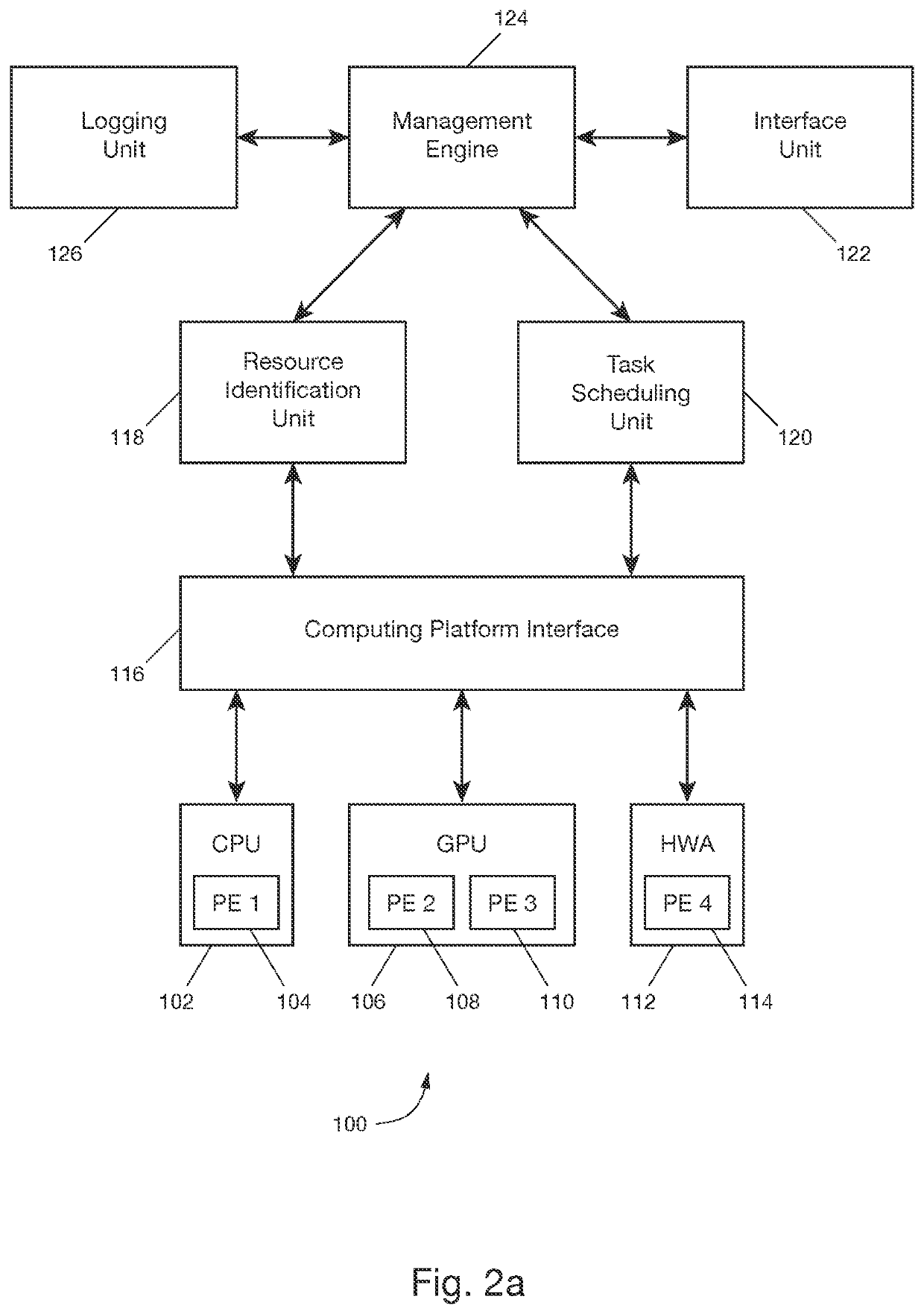
[0061]FIG. 2a: a device for synthesizing a correct-by-construction controller according to an exemplary embodiment of the invention

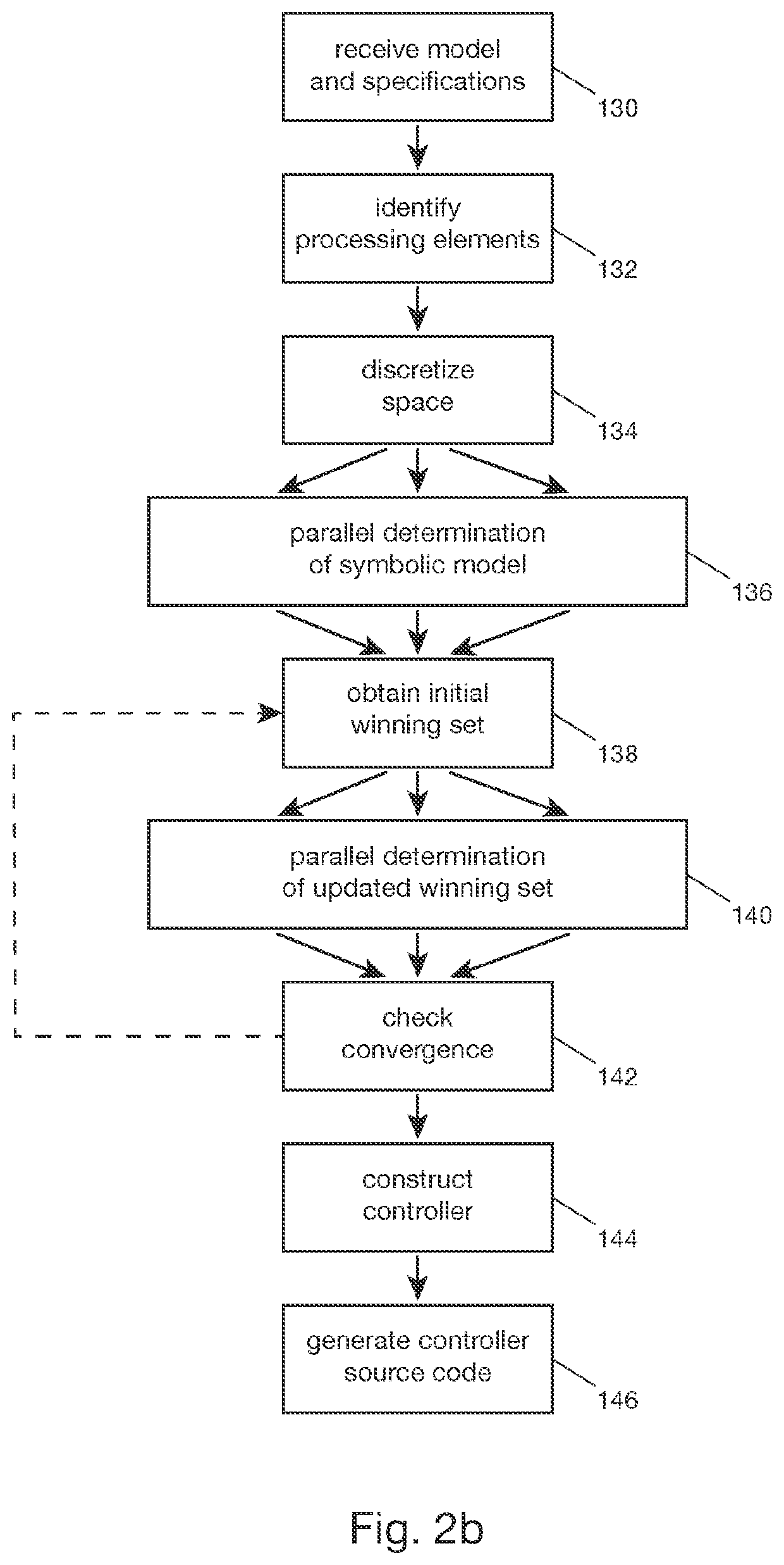
[0062]FIG. 2b: a flow chart of a method to synthesize a correct-by-construction controller in accordance with an embodiment of the invention

[0063]FIG. 3: a flow chart of a method to identify available processing elements according to an embodiment of the invention

[0064]FIG. 4a: a flow chart of a method for a parallel determination of a symbolic model in accordance with an embodiment of the invention

[0065]FIG. 4b: a parallel determination of a symbolic model according to an embodiment of the invention

[0066]FIG. 5a: a flow chart of a method for a parallel determination of an updated winning set in accordance with an embodiment of the invention

[0067]FIG. 5b: a parallel...


PUM


Abstract

A method includes: receiving a mathematical model of a control system, with state variables and control parameters; discretizing at least a part of a space to obtain a set of tuples; determining for each tuple at least one successor state; obtaining an initial winning set of tuples; determining an updated winning set of tuples, including comparing the at least one successor state with the initial winning set of tuples, where the comparison is distributed over available processing elements by choosing one processing element from the available processing elements for each tuple to perform the comparison and where the available processing elements are used simultaneously at least in part; repeating the determination of the updated winning set of tuples to obtain a new updated winning set of tuples if a convergence measure does not meet a criterion, and constructing a controller for the control system from the new updated winning set.

Description

BACKGROUNDTechnical Field[0001]The invention relates to a method and a device to synthesize correct-by-construction controllers for a control system.Description of the Related Art[0002]Autonomous physical systems like robots have become ubiquitous in industrial applications and recent advances in sensor and computer technology have opened up new possibilities like autonomous driving or interconnected networks of robots. The increasing complexity of such cyber-physical systems with a tight integration of physical systems, sensors, communication networks and computer systems, however, requires novel approaches for the control of these systems, which are capable of handling large amounts of data and required to work reliably in a variety of situations, in particular since guaranteeing safety is crucial in many applications.[0003]One technique to design suitable controllers is the synthesis of correct-by-construction controllers through symbolic controller synthesis, see P. Tabuada, “Ve...

Claims


Application Information

Patent Timeline
IPC IPC(8): G05B19/042G06F17/13G06F8/30
CPCG05B19/0426G05B2219/24168G06F8/30G06F17/13
Inventor MAHMOUD, MAHMOUD KHALED MOHAMEDZAMANI, MAJID
Owner TECH UNIV MUNCHEN
Learn More