Eureka AIR delivers breakthrough ideas for toughest innovation challenges, trusted by R&D personnel around the world.

Interrogation of optical fiber sensor networks

a technology of optical fiber and sensor network, applied in the field of optical fiber sensor network interrogation, can solve the problems of different time delay, low spatial resolution, tdm is the measurement time and low energy received by the interrogating equipment, etc., and achieve the effect of fast and accurate techniques

Active Publication Date: 2021-12-09
FBGS TECH GMBH +1
View PDF0 Cites 5 Cited by
  • Summary
  • Abstract
  • Description
  • Claims
  • Application Information

AI Technical Summary

Benefits of technology

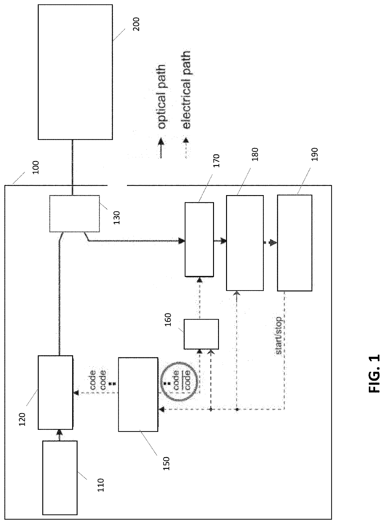
The present invention provides faster and more accurate techniques for reading optical fiber sensor networks. The invention allows for simultaneous interrogation of multiple sensors without the need for high-speed modulators, resulting in a quantitative and accurate output with good signal to noise ratio.

Problems solved by technology

Each FBG is located at a different location in an optical network wherein each location results in a different time delay due to different propagation lengths.
Since the interrogator has to wait for a full pulse round trip time before launching a new pulse the major disadvantages of TDM are the measurement time and the low energy received by the interrogating equipment.
This method has a good spatial resolution but is limited to short fiber lengths of around 10 to 70 m.

Method used


Image

  • Interrogation of optical fiber sensor networks
  • Interrogation of optical fiber sensor networks
  • Interrogation of optical fiber sensor networks

Examples


Embodiment Construction

[0066]The present invention will be described with respect to particular embodiments and with reference to certain drawings, but the invention is not limited thereto but only by the claims. The drawings described are only schematic and are non-limiting. In the drawings, the size of some of the elements may be exaggerated and not drawn on scale for illustrative purposes. The dimensions and the relative dimensions do not correspond to actual reductions to practice of the invention.

[0067]Furthermore, the terms first, second and the like in the description and in the claims, are used for distinguishing between similar elements and not necessarily for describing a sequence, either temporally, spatially, in ranking or in any other manner. It is to be understood that the terms so used are interchangeable under appropriate circumstances and that the embodiments of the invention described herein are capable of operation in other sequences than described or illustrated herein.

[0068]Moreover, ...


PUM


Abstract

A system for interrogating sensors in a fiber optical sensor network includes groups of sensors. The sensors in one group operate at different wavelengths, and the sensors of other groups may have overlapping wavelengths. A light source generates a broadband light signal, input and output means for guides the broadband light to the fiber optical sensor network for illuminating the sensors and for coupling the light signal coming from the sensors of the fiber optical sensor network to the detection system, and a detection system detects the received light signal, during a detection integration time. The system is arranged for selecting pre-dominantly the received light coming from the different sensors of a selected group of sensors using a code-division multiplexing technique and simultaneously detecting sensors of the selected group of sensors wavelength-division multiplexing technique.

Description

FIELD OF THE INVENTION[0001]The present invention relates to the field of optics. More particularly, the present invention relates to systems and methods for interrogating optical fiber sensor networks in a fast and accurate way using multiplexing techniques.BACKGROUND OF THE INVENTION[0002]In present days, networks of optical sensors gain a lot of attention. In terms of “smart structures”, where high numbers of sensors are required to monitor the condition of a material or system, optical fiber sensor networks are an essential part of the system. By means of these networks that are small and light, and independent of electro-magnetic interference, it is possible to implement sensors measuring strain, temperature or other parameters into a setup. To achieve a high spatial measurement resolution, the density of sensors needs to be as high as possible, preferably in a single optical fiber. In the following example, optical sensors are referred to as Fiber Bragg Gratings (FBGs). Addres...

Claims


Application Information

Patent Timeline
IPC IPC(8): G01D5/353
CPCG01D5/35316G01D5/35387G01D5/35335G01D5/35341G01D5/35396
Inventor LINDNER, ERICVLEKKEN, JOHANVAN HOE, BRAMVOIGTLANDER, CHRISTIANVAN ROOSBROECK, JAN RENELOCHMANN, STEFFENAHRENS, ANDREASGOTTEN, MAREK
Owner FBGS TECH GMBH
Why Eureka
Eureka Blog
Learn More