
Combine harvester concave threshing bar

a harvester and concave technology, applied in the direction of threshers, peptides, drug compositions, etc., can solve the problems of inefficient harvesting, damaged and wasted crops, inefficient harvesting, etc., and achieve the effect of reducing the amount of grain damag

Active Publication Date: 2021-12-09
ROBERTSON BRIAN G
View PDF0 Cites 0 Cited by
  • Summary
  • Abstract
  • Description
  • Claims
  • Application Information

AI Technical Summary

Benefits of technology

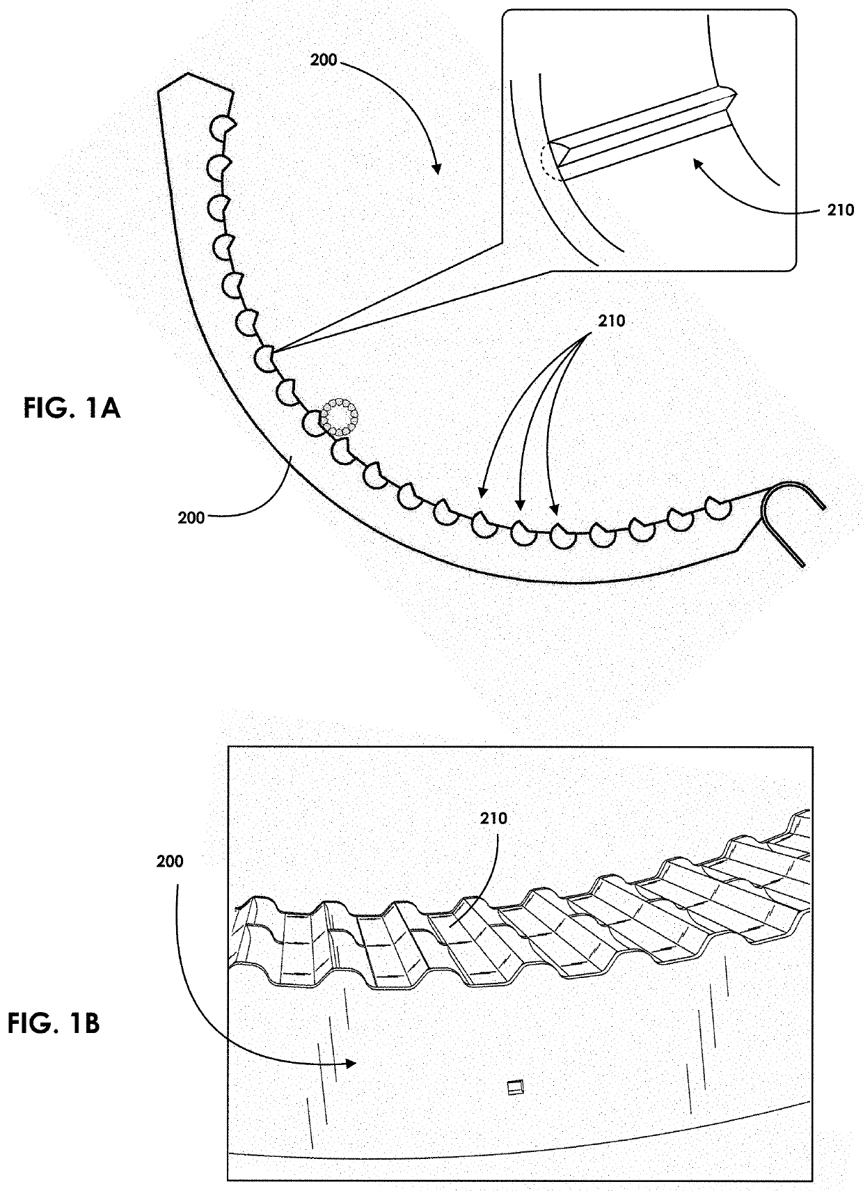
[0006]In one aspect of the disclosure described herein, a concave bar configuration provides a balance of being as aggressive as possible while doing the least amount of grain damage. The concave bar configuration of the disclosure described herein can thresh crop effectively such it has the most chance to be captured in a combine, while also threshing the crop with the least amount of grain damage, such that the seed or grain is without cracks or splits.
[0010]In another aspect the threshing bar can be comprised of dihedral faces that are laser hardened. In this method, the threshing bar metal can be hardened by a laser such that it maintains the bar angle and extends the bars life, otherwise the threshing surface (face of the bar) can get worn down and becomes less effective. In another aspect the threshing bar can be comprised of dihedral faces that is case hardened. In this method of hardening steel, however, the laser hardening is more precise and cost effective. With case hardening, one can harden the entire bar relative to a laser where one can harden a specific area. In another aspect, wherein the sharp edges of the threshing bar can be made less sharp (rounded off) and laser hardened. Here, this would provide for maximum bar life by just barely rounding off the sharp threshing edge, which are usually the first to get worn down, then case hardening that edge giving it maximum efficiency. Accordingly, by taking the small edge down exposes more surface area that can be hardened, which would become exposed more quickly. In another aspect, the threshing bar can be extruded.

Problems solved by technology

However, current conventional concave bars and separation grates have certain configurations that are not optimized to minimize grain damage while simultaneously maximizing threshing and separating of the crop material, thereby resulting in inefficient harvesting, damaged, and wasted crop.
However, if the crop does not get threshed until the second concave, then it only has a one-third probability for the threshed grains to fall through the concave openings.
Further, if the crop is not threshed in the second concave, then the third concave can become overloaded with crop and grain material and operating at over capacity, thus resulting in the grain being discharged out the back of the combine and resulting in very inefficient harvesting.

Method used


Image

  • Combine harvester concave threshing bar
  • Combine harvester concave threshing bar
  • Combine harvester concave threshing bar

Examples


Embodiment Construction

[0026]In the Brief Summary of the present disclosure above and in the Detailed Description of the disclosure described herein, and the claims below, and in the accompanying drawings, reference is made to particular features (including method steps) of the disclosure described herein. It is to be understood that the disclosure of the disclosure described herein in this specification includes all possible combinations of such particular features. For example, where a particular feature is disclosed in the context of a particular aspect or embodiment of the disclosure described herein, or a particular claim, that feature can also be used, to the extent possible, in combination with and / or in the context of other particular aspects and embodiments of the disclosure described herein, and in the disclosure described herein generally.

[0027]The embodiments set forth below represent the necessary information to enable those skilled in the art to practice the disclosure described herein and i...


PUM

PropertyMeasurementUnit
angleaaaaaaaaaa
lengthaaaaaaaaaa
surface areaaaaaaaaaaa

Abstract

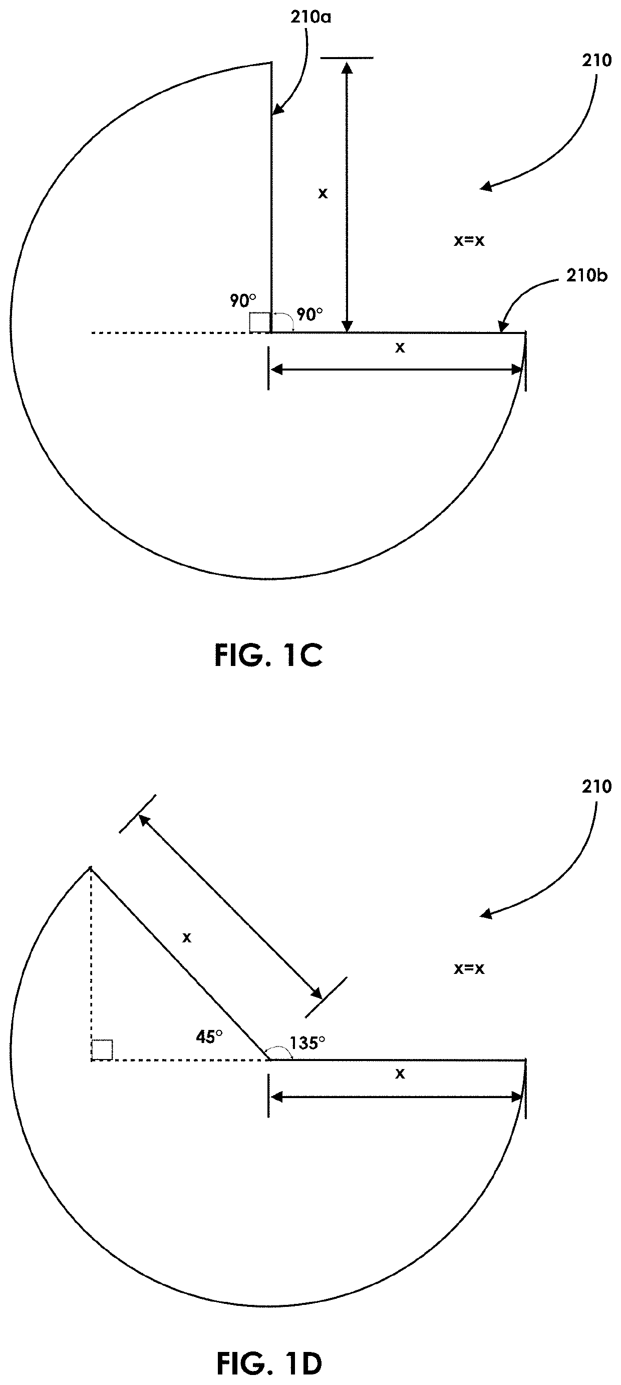
A threshing concave assembly is disclosed having a threshing concave bar wherein the threshing bar is comprised of two threshing surfaces having a dihedral angle relationship relative to each other. In addition, in another aspect the threshing bar can be comprised of two dihedral surfaces whereby one surface face has about 130% greater surface area than its adjacent surface face. Alternatively, one surface face of the threshing bar can be 1.3x wider than its adjacent surface face. In another aspect the threshing bar can be comprised of two dihedral surfaces whereby one surface face has about a 170% greater surface area than its adjacent surface face.

Description

CROSS-REFERENCE TO RELATED APPLICATIONS[0001]This application claims the benefit of U.S. Provisional Application No. 62 / 821,570 filed on Mar. 21, 2019, which is incorporated herein by reference. This application is also a continuation-in-part (CIP) of U.S. Non-Provisional application Ser. No. 16 / 115,331 filed on Aug. 28, 2018, which is incorporated herein by reference in its entirety, which is a CIP of U.S. Non-Provisional application Ser. No. 15 / 856,381 filed on Dec. 28, 2017, which is incorporated herein by reference in its entirety, and a CIP of U.S. Non-Provisional application Ser. No. 15 / 856,402, filed on Dec. 28, 2017, which is incorporated herein by reference in its entirety. This application is also a CIP of U.S. Design patent application Ser. No. 29 / 680,208 filed on Feb. 14, 2019, which is incorporated herein by reference in its entirety. This application is also a CIP of U.S. Design patent application Ser. No. 29 / 670,114 filed on Nov. 13, 2018, which is incorporated herein...

Claims


Application Information

Patent Timeline
Patent Type & Authority Applications(United States)
IPC IPC(8): C07K16/40C07K16/28C12N15/62A61P35/00
CPCC07K16/40C07K16/2809C07K16/2863C12N15/62A61K2039/505C07K2317/73C07K2317/24C07K2317/64C07K2317/622A61P35/00A01F12/24A01F7/04A01F7/06A01F12/26
Inventor ROBERTSON, BRIAN G.
Owner ROBERTSON BRIAN G
Learn More