Powering microcontrollers

Active Publication Date: 2021-12-02
KONINKLJIJKE PHILIPS NV
View PDF0 Cites 0 Cited by
  • Summary
  • Abstract
  • Description
  • Claims
  • Application Information

AI Technical Summary

Benefits of technology

This patent describes a way for a microcontroller to take in an alternating current (AC) and efficiently convert it into a direct current (DC) to power itself. This is done by using a special switch that prevents unwanted discharge of capacitance when the voltage of the AC waveform is lower than the high-side DC voltage rail. This allows the microcontroller to be powered from its own AC source, such as a wireless power receiver or an energy harvesting module. The microcontroller can also output control signals to control the operation of a host device in which it is embedded. Overall, this invention allows for a more efficient and flexible way to power a microcontroller and control its host device.

Problems solved by technology

In some instances however, depending on the location of the microcontroller within the product, providing suitable DC power to the microcontroller from a power source of the product, e.g. from a battery or derived from a mains-supply, may not be straightforward.

Method used


Image

  • Powering microcontrollers
  • Powering microcontrollers
  • Powering microcontrollers

Examples


Embodiment Construction

[0028]Various types of electronic shaver products are known. Such products typically have one or more movable cutting elements that, in use, are driven to provide a cutting action. For instance in some shaver products one or more rotatable cutting elements may be provided.

[0029]An improved or personalised user experience may be realised by sensing shaving conditions during shaving and adapting at least one aspect of the shaver operation to the sensed conditions. In some instances it may be beneficial to respond to the conditions at the cutting element, and thus it has been proposed to provide sensing and / or control at the location of the cutting element. At least some aspects of sensing and control may be provided by a microcontroller located at the location of the cutting element, for instance a microcontroller may be located on, or as part of, the structure of a rotating cutting element.

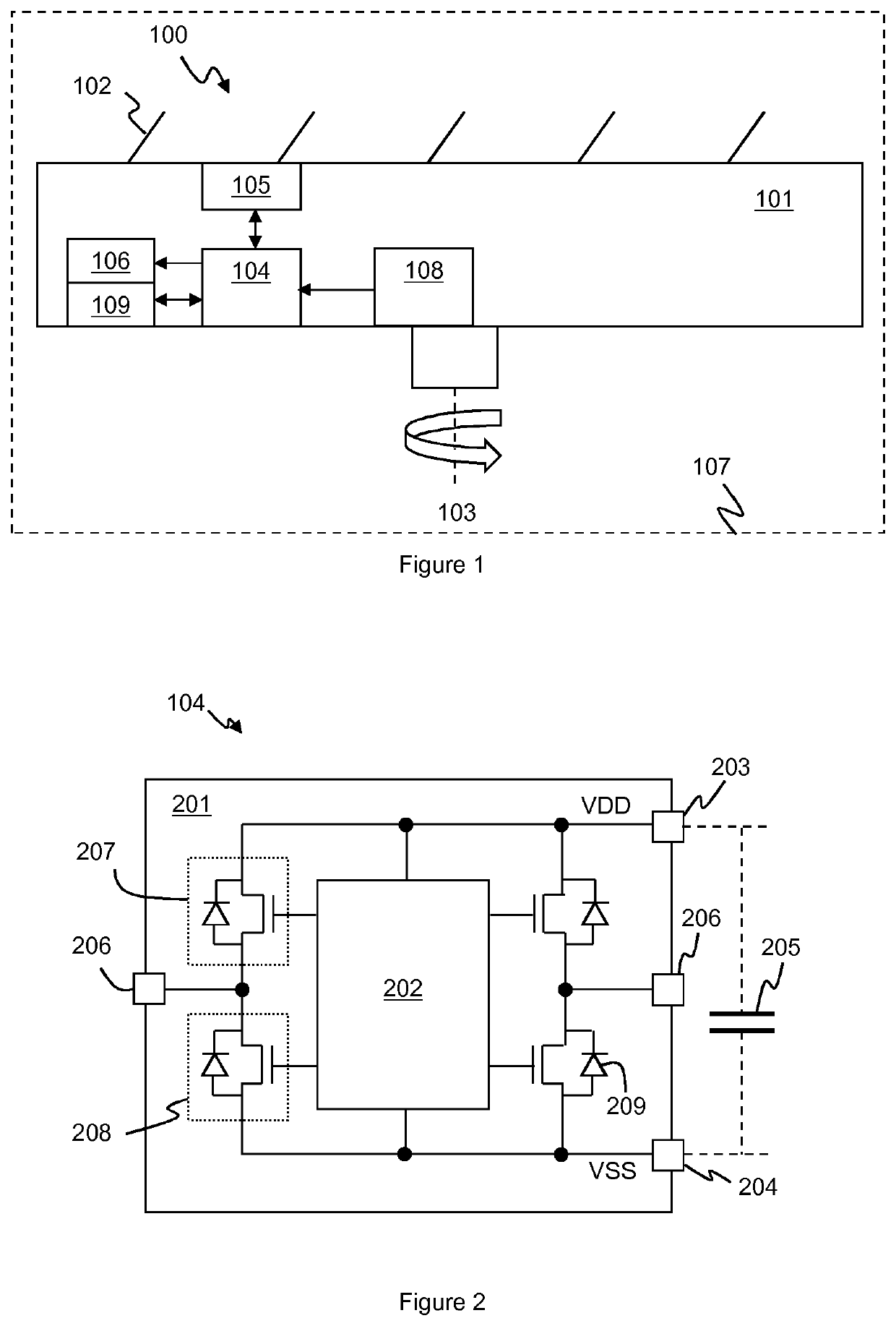
[0030]FIG. 1 illustrates this principle. FIG. 1 illustrates generically a cutting element 100. ...


PUM


Abstract

This application relates to methods and apparatus for powering microcontrollers (104), in particular for powering microcontrollers of a personal care product, such as a shaver product (107). The microcontroller is arranged such that a first output port (206-1) of a plurality of output ports of the microcontroller receives, in use, an AC waveform. Each output port has an associated high-side switch (207) electrically connected between the output port and a high-side DC voltage rail and an associated low-side switch (208) electrically connected between the output port and a low-side DC voltage rail. A processing module (202) of the microcontroller is configured to monitor a phase of the AC waveform and to control switching of the associated high-side and low-side switches of the first output port based on the phase of the AC waveform so as to provide a rectified voltage between the high-side DC voltage rail and the low-side voltage rail for powering the processing module. The processing module (202) also controls switching of the associated switches of at least a further output port to output a control signal for controlling at least one aspect of operation of a host device. The processing module is further configured to maintain the associated high-side switch of the first output port in a turned-off state when a monitored voltage of the AC waveform at the first output port is between zero and a monitored voltage at the high-side DC voltage rail, and to maintain the associated high-side switch of the first output port in a turned-on state when the monitored voltage of the AC waveform at the first output port is greater than the monitored voltage at the high-side DC voltage rail.

Description

FIELD OF THE INVENTION[0001]This disclosure relates to powering of microcontrollers, in particular for powering microcontrollers of a personal care product, such as a shaver product.BACKGROUND OF THE INVENTION[0002]Microcontrollers are relatively small control circuits, typically having at least one processor and some memory and configurable to provide some sensing and / or control functionality via a variety of general purpose input-output (GPIO) ports.[0003]Microcontrollers may be embedded into a variety of electronic products to provide sensing and / or control functionality, for instance to allow operation of the product to be adapted to the prevailing operating conditions.[0004]The microcontroller will need to be powered in use. In some instances however, depending on the location of the microcontroller within the product, providing suitable DC power to the microcontroller from a power source of the product, e.g. from a battery or derived from a mains-supply, may not be straightfor...

Claims


Application Information

Patent Timeline
IPC IPC(8): H02M7/219H02M1/088H02M1/08H02M1/00G01R19/165G01R19/175B26B19/38
CPCH02M7/219H02M1/088H02M1/082H02M1/083B26B19/3873H02M1/0003G01R19/16538G01R19/175H02M1/0048H02M1/08H02M1/081H02M5/4585H02M7/217
Inventor VELTMAN, EDDY GERRIT
Owner KONINKLJIJKE PHILIPS NV
Why Eureka
Try Eureka