
Radio reception apparatus, radio communication system, and radio receiving method

Active Publication Date: 2021-11-25
NEC CORP
View PDF4 Cites 0 Cited by
  • Summary
  • Abstract
  • Description
  • Claims
  • Application Information

AI Technical Summary

Benefits of technology

The patent aims to provide a radio reception device, system, and method that can reduce errors in signal reception while keeping the format of the signal frame minimal.

Problems solved by technology

There is a problem that, when a priority frame has been input from a wired port while a radio transmission apparatus is transmitting a non-priority frame in a radio section, it is required to wait until completion of transmission of a non-priority frame with respect to reading out the priority frame, which causes a delay variation of the priority frame.
However, there is a problem, in the communication apparatus disclosed in Japanese Unexamined Patent Application Publication No. 2014-049935 described above, that the non-priority frame whose transmission has been intentionally interrupted is recognized as a broken frame on a receiving side and erroneously recorded as a reception error, which is a so-called pseudo error.
Further, while a Frame Check Sequence (FCS) is typically added to the end of a frame, there is a problem, in the communication system disclosed in Japanese Unexamined Patent Application Publication No. 2005-159792 described above, that there is a significant change in the frame format.

Method used


Image

  • Radio reception apparatus, radio communication system, and radio receiving method
  • Radio reception apparatus, radio communication system, and radio receiving method
  • Radio reception apparatus, radio communication system, and radio receiving method

Examples


first example embodiment

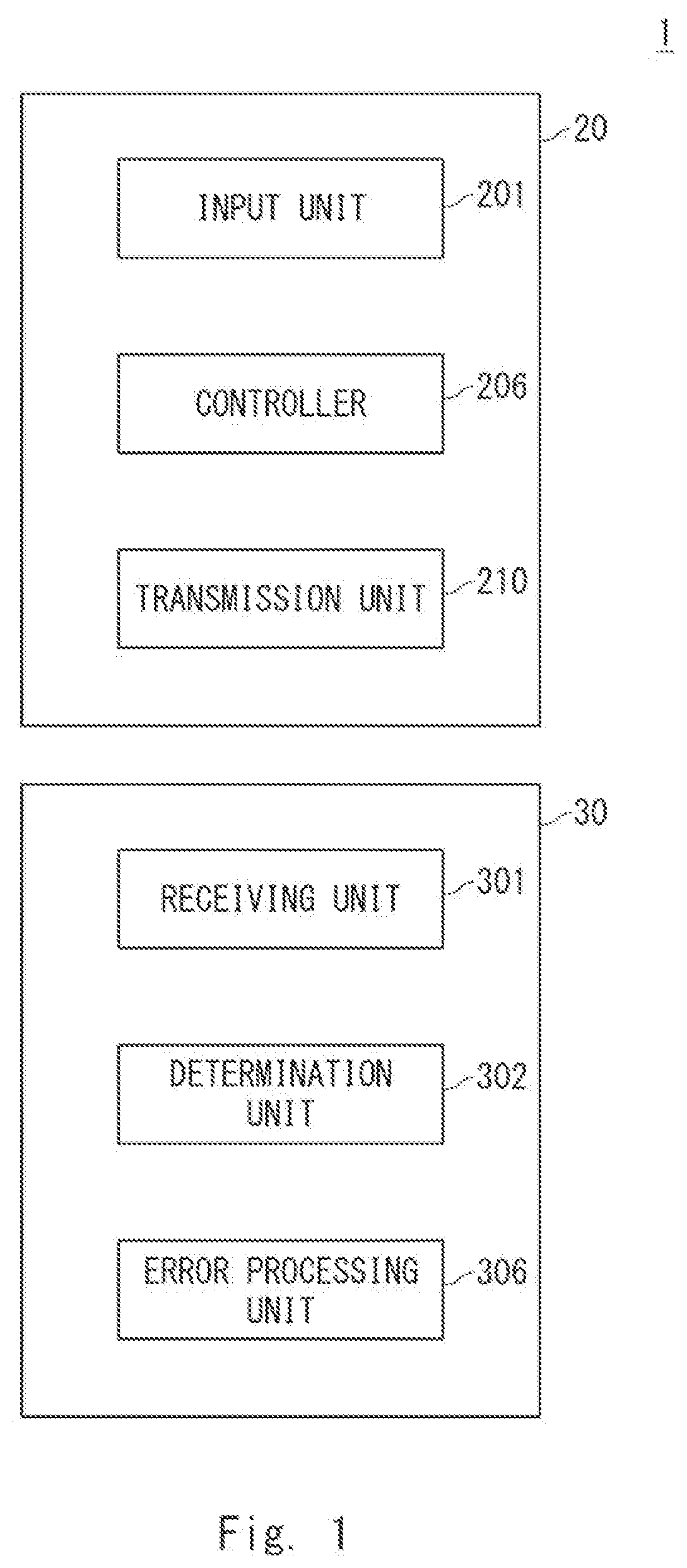
[0054]Referring first to FIG. 1, a first example embodiment according to the present disclosure will be described. FIG. 1 is a block diagram showing a configuration of a radio communication system 1 according to the first example embodiment.

[0055]The radio communication system 1 includes a radio transmission apparatus 20 and a radio reception apparatus 30.

[0056]The radio transmission apparatus 20 includes an input unit 201, a controller 206, and a transmission unit 210.

[0057]The input unit 201 accepts input of a frame.

[0058]The controller 206 supplies the frame input by the input unit 201 to the transmission unit 210.

[0059]The transmission unit 210 transmits the frame supplied from the controller 206 to the radio reception apparatus 30.

[0060]The frame is classified as a priority frame or a non-priority frame. The controller 206 interrupts, in response to input of a priority frame during transmission of a non-priority frame, supply of the non-priority frame to the transmission unit 2...

second example embodiment

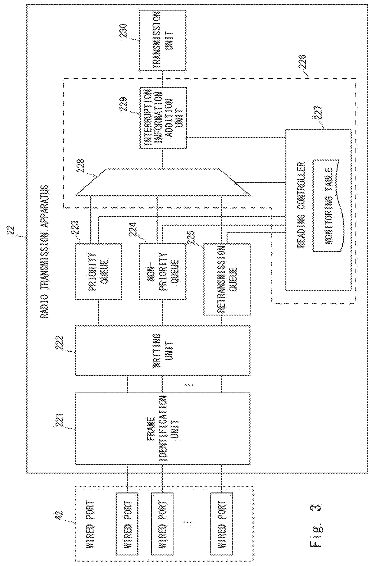
[0070]Referring next to FIGS. 2-9, a second example embodiment according to the present disclosure will be described. FIG. 2 is a block diagram showing one example of a system to which a radio communication system (which is hereinafter referred to as a radio communication apparatus) 2 according to the second example embodiment can be applied. The system constructs a relay line that relays two lines wirelessly. The system includes a plurality of radio communication apparatuses 2a and 2b and a relay line 8. In the following, when it is not necessary to differentiate radio communication apparatuses 2a and 2b, the radio communication apparatuses 2a and 2b may be simply referred to as a radio communication apparatus 2. While the number of radio communication apparatuses 2 included in the system is set to two for the sake of simplification of the description, the number of radio communication apparatuses 2 may be larger than two.

[0071]The relay line 8 is a relay line such as a backhaul li...

third example embodiment

[0138]Referring next to FIGS. 10-12, a third example embodiment according to the present disclosure will be described. While a radio transmission apparatus 22 according to the third example embodiment has a configuration similar to that of the radio transmission apparatus 22 according to the second example embodiment, they are different from each other in that the radio transmission apparatus 22 according to the third example embodiment changes the frame format on demand. FIGS. 10A and 10B are diagrams showing one example of the frame format according to the third example embodiment. When a priority frame has been input during transmission of a non-priority frame, as shown in FIG. 10A, the interruption information addition unit 229 of the controller 226 of the radio transmission apparatus 22 according to the third example embodiment adds the interruption information to a predetermined bit position of the priority frame and supplies the obtained frame to the transmission unit 230. Th...


PUM


Abstract

A radio reception apparatus and the like capable of eliminating a pseudo reception error while minimizing a change in a frame format are provided. A radio reception apparatus 30 according to the present disclosure includes: a receiving unit 301 configured to receive a frame from a radio transmission apparatus 20; a determination unit 302 configured to determine, using the frame received from the radio transmission apparatus 20, whether or not transmission of a preceding frame that has been received from the radio transmission apparatus 20 before receiving of the frame has been interrupted; and an error processing unit 306 configured to eliminate a reception error regarding the preceding frame in accordance with a determination that the transmission of the preceding frame has been interrupted.

Description

INCORPORATION BY REFERENCE[0001]This application is based upon and claims the benefit of priority from Japanese patent application No. 2020-87867, filed on May 20, 2020, the disclosure of which is incorporated herein in its entirety by reference.TECHNICAL FIELD[0002]The present disclosure relates to a radio reception apparatus, a radio communication system, and a radio receiving method.BACKGROUND ART[0003]In mobile networks, frames (priority frames) where it is required to reduce a delay variation, like Precision Time Protocol (PTP), and other frames (non-priority frames) are used in a mixed manner. There is a problem that, when a priority frame has been input from a wired port while a radio transmission apparatus is transmitting a non-priority frame in a radio section, it is required to wait until completion of transmission of a non-priority frame with respect to reading out the priority frame, which causes a delay variation of the priority frame.[0004]In order to solve the above p...

Claims


Application Information

Patent Timeline
IPC IPC(8): H04L1/00H04W28/04
CPCH04L1/0045H04L1/0061H04W28/04H04L1/1887H04L47/28H04L47/6215
Inventor IGARASHI, AOI
Owner NEC CORP
Learn More