
Direct fabrication of aligners with interproximal force coupling

a technology of interproximal force coupling and aligner, which is applied in the field of can solve the problems of complex tooth movement, unsatisfactory prior methods and apparatus for moving teeth, and patient attachments on the teeth can be somewhat cumbersome, so as to improve the movement of teeth, improve the accuracy of tooth movement, and increase the amount of tooth surfa

Pending Publication Date: 2021-11-18
ALIGN TECH
View PDF4 Cites 0 Cited by
  • Summary
  • Abstract
  • Description
  • Claims
  • Application Information

AI Technical Summary

Benefits of technology

This approach enables more precise and efficient tooth movement, improving anchoring and rotation control, allowing for effective treatment of diastema and midline shifts, while reducing the need for multiple attachments, thereby enhancing the accuracy and efficiency of orthodontic treatments.

Problems solved by technology

Prior methods and apparatus for moving teeth can be less than ideal in at least some respects.
Although transparent shell appliances can be effective in moving teeth, complex tooth movements may benefit from the use of attachments on the teeth that engage the appliance to move the tooth.
Although attachments can be effective, the attachments on the teeth can be somewhat cumbersome for the patient.

Method used


Image

  • Direct fabrication of aligners with interproximal force coupling
  • Direct fabrication of aligners with interproximal force coupling
  • Direct fabrication of aligners with interproximal force coupling

Examples


Embodiment Construction

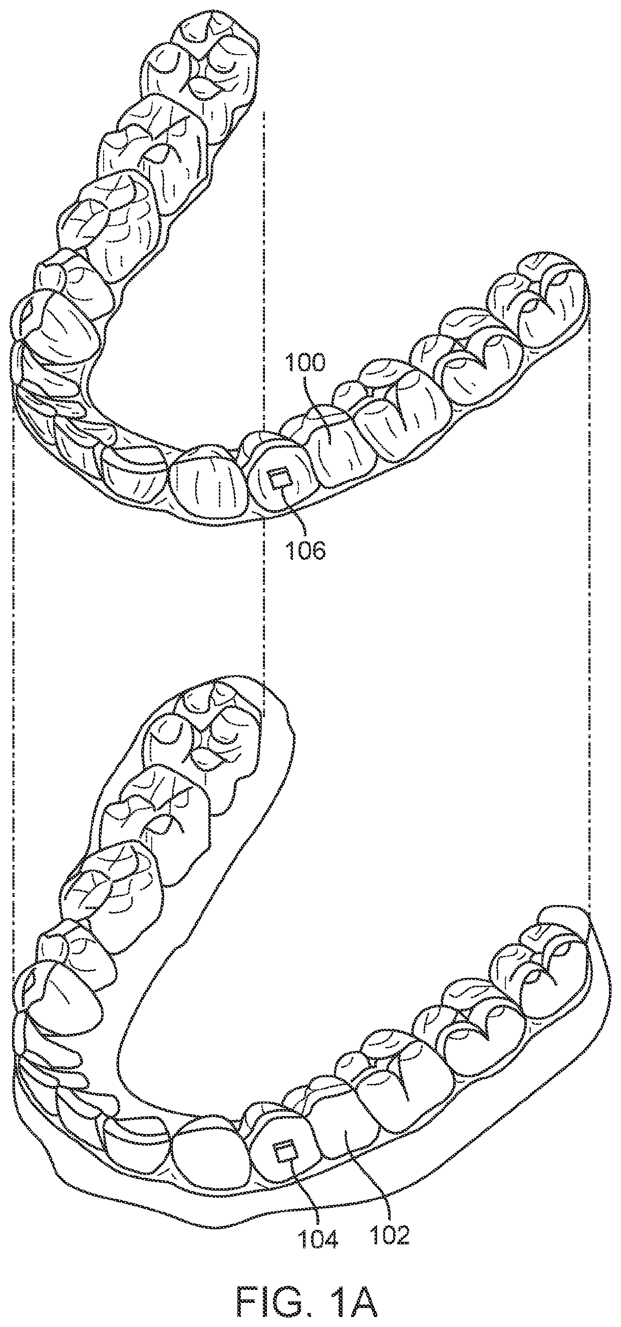
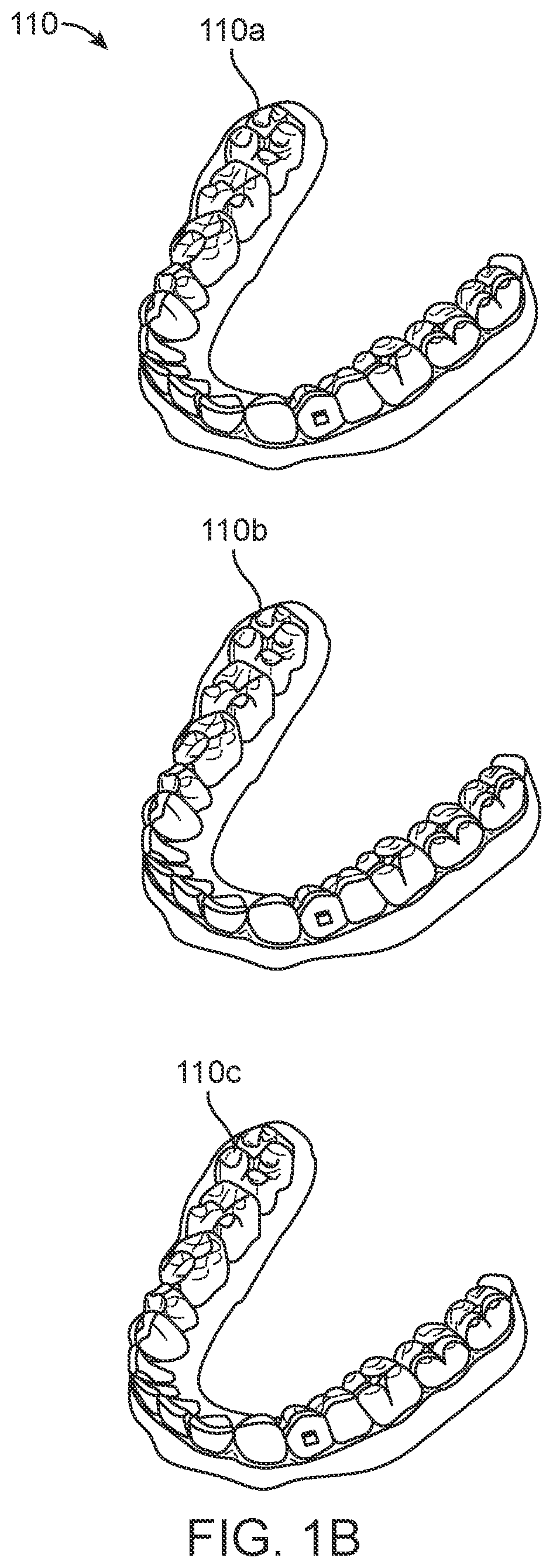
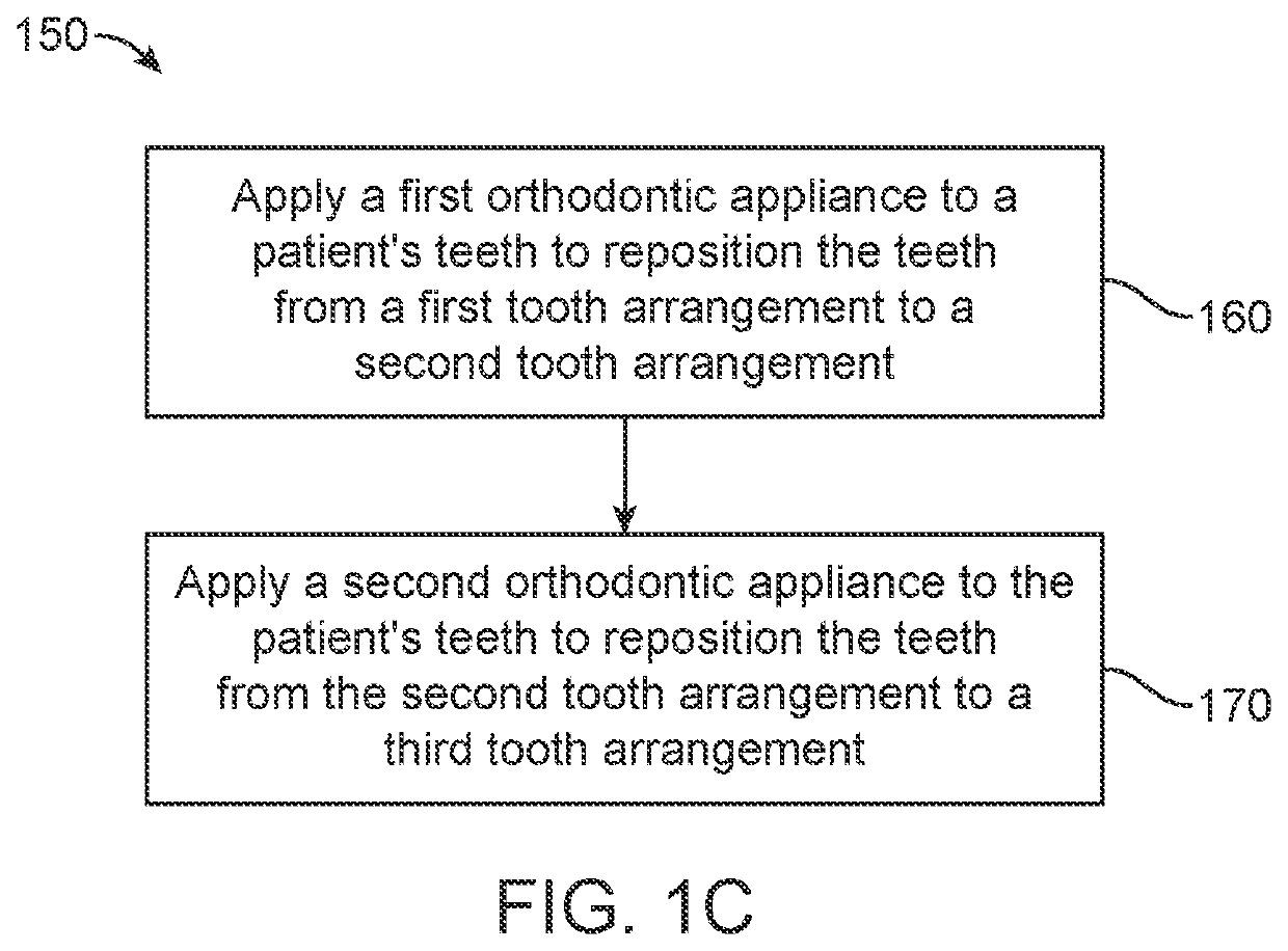
[0037]In many embodiments, a method of moving a tooth of a patient from a first position and orientation to a second position and orientation is provided. The method comprises providing a polymeric shell appliance shaped to fit a plurality of teeth. The polymeric shell appliance comprises a polymeric interproximal engagement structure sized to extend across an interproximal space of the tooth from a lingual side to a buccal side. The polymeric shell appliance also comprises one or more teeth receiving cavities to couple the tooth to one or more other teeth of the plurality with one or more other tooth receiving cavities. When worn, the interproximal engagement structure applies a force to the tooth from the interproximal space and moves the tooth from the first position and orientation to the second position and orientation.

[0038]In some embodiments, each of the interproximal engagement structures comprises a width extending between adjacent teeth defining the interproximal space, a...


PUM


Abstract

Polymeric shell appliances are provided in which the polymeric shell appliances are configured to provide one or more activation forces to facilitate tooth movement. In many embodiments, the appliances comprise interproximal engagement structures to provide activation forces to interproximal tooth surfaces. In many embodiments, the activation forces are arranged to provide a plurality of forces, including a force in a direction opposite to an intended direction of tooth movement. The polymeric shell appliances may comprise one or more tooth receiving cavities, in which each of the plurality of tooth receiving cavities is shaped and arranged to provide a counter moment of each of the plurality of teeth.

Description

CROSS-REFERENCE[0001]This application is a continuation of U.S. application Ser. No. 15 / 202,472, filed Jul. 5, 2016, which claims the benefit of U.S. Provisional Application No. 62 / 189,263, filed Jul. 7, 2015, the disclosures of which are incorporated herein by reference in their entirety.[0002]The subject matter of the following co-pending patent applications is related to the present application: U.S. application Ser. No. 15 / 202,342, filed Jul. 5, 2016, entitled “MULTI-MATERIAL ALIGNERS,” which claims the benefit of U.S. Provisional Application No. 62 / 189,259, filed Jul. 7, 2015 and U.S. Provisional Application No. 62 / 189,282, filed Jul. 7, 2015; U.S. application Ser. No. 15 / 202,452, filed Jul. 5, 2016, entitled “DIRECT FABRICATION OF ALIGNERS FOR ARCH EXPANSION,” which claims the benefit of U.S. Provisional Application No. 62 / 189,271, filed Jul. 7, 2015, and U.S. Provisional Application No. 62 / 189,301, filed Jul. 7, 2015; U.S. application Ser. No. 15 / 202,348, filed Jul. 5, 2016, ...

Claims


Application Information

Patent Timeline
Patent Type & Authority Applications(United States)
IPC IPC(8): A61C7/08
CPCA61C7/08B33Y10/00A61C7/002B33Y80/00
Inventor KOPELMAN, AVIMORTON, JOHN
Owner ALIGN TECH
Learn More