
Toilet splash guard device

a technology for guarding devices and toilets, which is applied in water installations, lavatory sanitory, construction, etc., can solve problems such as affecting the cleanliness of the toilet area, causing the discharge of urine, and causing splashing or splattering on the sides of the toilet, so as to achieve efficient discharge of liquid into the bowl and its water, and the effect of dispersing the stream

Active Publication Date: 2021-11-11
SPLASH GUARD
View PDF0 Cites 0 Cited by
  • Summary
  • Abstract
  • Description
  • Claims
  • Application Information

AI Technical Summary

Benefits of technology

[0008]In still another embodiment, the deflection plate can face generally upward rather than toward the front rim of the toilet. The deflection plate can be suspended an inch or less, or several inches above a level of liquid, such as water, in the toilet. The deflection plate can be generally planar, and a lower planar surface can be angled relative to the water level, for example, at an angle of between 0 degrees and 80 degrees, inclusive, or between 30 degrees and 60 degrees, inclusive. Such angle can appropriately absorb the impact of an impinging liquid stream, and deflect the liquid into the bowl and its water efficiently.
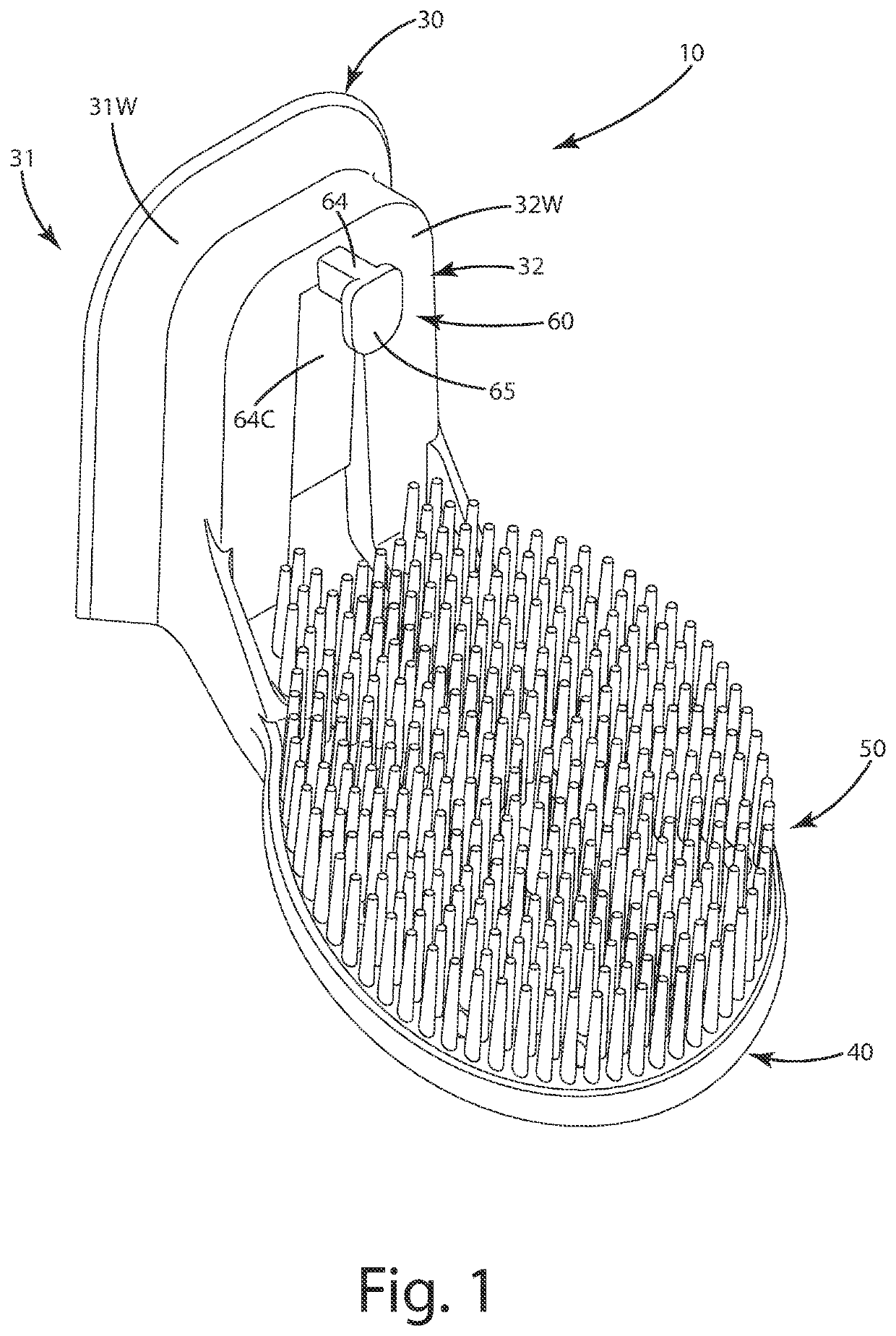
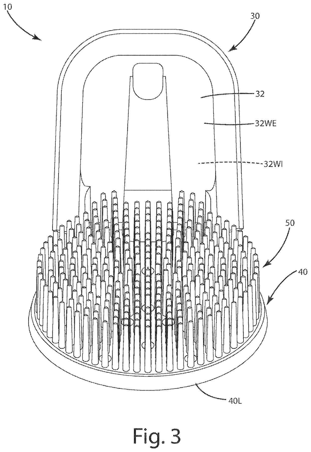
[0009]In even another embodiment, the deflection plate can include an upper surface. The optional multiple fingers can extend upward from the upper surface. The fingers can be constructed from a resilient material and can taper down in dimension as each finger extends farther from the deflection plate. The fingers can further assist in absorbing the impact of the impinging liquid stream, dissipate the stream, and yet allow the resulting liquid to travel between adjacent fingers, downward and off a lower edge of the deflection plate.
[0017]The current embodiments of the splatter suppression device and related method of use provide benefits in preventing or impairing splatter from urination by upright individuals that previously have been unachievable. For example, where the device and its components are designed to be placed on a side rim of the toilet, they do not get in the way of other seated use of the toilet, so the device need not be moved for such seated use. Where the device and the deflection plate are relatively low profile, extending optionally 1 to 4 inches, inclusive, or 2 to 3 inches, inclusive, from the side rim, the device further does not impair seated use of the toilet. Where included, the downward inclined angle of the deflection plate provides appropriate deflection of a liquid stream from above the toilet. The deflection plate can efficiently fragment the stream and direct the stream toward the underlying water in the toilet. Where the fingers are included, the fingers can further dissipate the impact of the liquid stream from above, and assist in channeling the liquid off the deflection plate at a lower end, or through holes defined by the plate and interspersed among the fingers. Where the device includes a transfer element, a replacement splatter suppression device can be used to engage and remove an already installed device without the user having to contact it. This can reduce anxiety for the user in performing the replacement task and improve sanitation.

Problems solved by technology

Usage of a toilet by a male in a standing orientation typically creates issues with regard to the toilet and the surrounding area.
The stream of urine may also be misdirected and splash or splatter on the sides of the bowl, again upward and out of the toilet—or miss the bowl altogether.
The resultant splattering leaves the toilet area in an unpleasant and unsanitary condition, requiring cleaning and odor abatement action by the user or others.
These guards also are difficult to replace in a sanitary manner.
Where the guard is older, there can be malodorous build up on the guard that is unpleasant to contact and / or clean.
Further, many conventional guards are placed centrally in the toilet bowl, which can increase the likelihood of contact with the guard when a user is seated on the toilet.

Method used


Image

  • Toilet splash guard device
  • Toilet splash guard device
  • Toilet splash guard device

Examples


Embodiment Construction

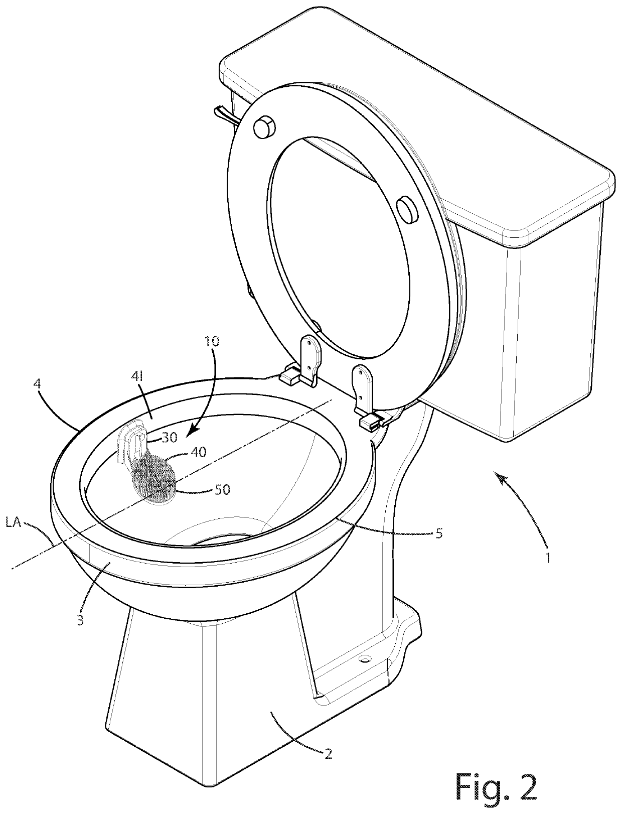
[0030]A current embodiment of the splash suppression device or splash guard is illustrated in FIGS. 1-5, and generally designated 10. The splash suppression device 10 generally includes a base 20, an arm 30 that removably attaches to the base 20, and a deflection plate 40 as described below. The device 10 can be used in conjunction with a variety of lavatory and restroom structures, but is described here in connection with a toilet 1. The toilet 1 as shown in FIG. 2 can include a toilet pedestal 2, a front rim 3 which is the forward most portion of the toilet, and first 4 and second 5 side rims, which lay across a longitudinal axis LA from one another. The toilet further includes a bowl 7 that typically has water W in it. The water typically forms a water level WL. The side rim 4 can include an interior rim surface 41.

[0031]The device can be secured to the toilet, and in particular to a side rim. As shown in FIGS. 5, the base 20 can be joined with and engage the interior surface 41 ...


PUM


Abstract

A urine splatter suppression device and related method are provided. The device can include a base that engages a rim of a toilet, an arm including a corresponding recess and / or projection that engages a base recess and / or a base projection so that the arm is removably supported by the base adjacent the rim, and a deflection plate is joined with the arm and angled between 60 degrees and 90 degrees inclusive relative to the arm and extending transversely inward toward the longitudinal axis of the toilet from the side rim of the toilet. Multiple fingers can extend upward from the deflection plate. The device can be configured so a stream of liquid impinging the plate and / or fingers from above the toilet is dissipated to impair splatter of the stream to an area outside the toilet. A related method of use also is provided.

Description

BACKGROUND OF THE INVENTION[0001]The present invention relates to lavatory accessories, and more particularly to a splash guard device for use with a toilet.[0002]Usage of a toilet by a male in a standing orientation typically creates issues with regard to the toilet and the surrounding area. For example, when most males urinate into a toilet, the stream of urine typically splatters water, in the bowl of the toilet, upward and out of the toilet. The stream of urine may also be misdirected and splash or splatter on the sides of the bowl, again upward and out of the toilet—or miss the bowl altogether. The resultant splattering leaves the toilet area in an unpleasant and unsanitary condition, requiring cleaning and odor abatement action by the user or others.[0003]There are a variety of urine splash or splatter guards in the market. Some guards drape a fabric over the water in the bowl to reduce splatter. Other guards have an arm that clips to the front rim of the bowl and extends alon...

Claims


Application Information

Patent Timeline
Patent Type & Authority Applications(United States)
IPC IPC(8): E03D9/00
CPCE03D9/00
Inventor HERBERT, BRANDON E.
Owner SPLASH GUARD
Learn More