Electric stapler

a stapler and electric technology, applied in the field of electric staplers, can solve the problems of accidental striking, more dangerous electric staplers, and inability to prevent safety mechanisms mentioned above, and achieve the effect of preventing accidental striking

Active Publication Date: 2021-11-11
APEX MFG
View PDF0 Cites 0 Cited by
  • Summary
  • Abstract
  • Description
  • Claims
  • Application Information

AI Technical Summary

Benefits of technology

[0005]The main object of the present invention is to provide an electric stapler which is able to prevent from accidently striking. In addition, the user can be informed whether the stapler is strikable or not.

Problems solved by technology

Thus, the electric staplers are more dangerous.
However, the safety mechanisms mentioned above have some disadvantages.
First, accidentally striking cannot be prevented because the trigger button is closed to the safety button, or the trigger button and the safety button are the same button.
Second, when the trigger button and the safety button are pressed at the same time by other objects, the staple may be struck out accidentally.
Third, if the safety button is designed to be difficult to unlock, the stapler becomes inconvenient to use.

Method used


Image

  • Electric stapler
  • Electric stapler
  • Electric stapler

Examples


Embodiment Construction

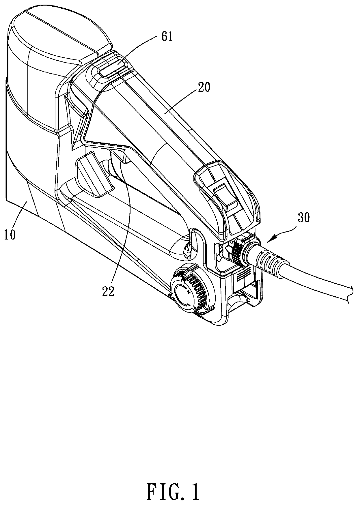
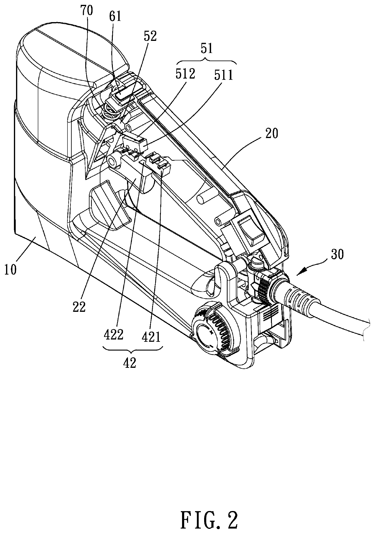
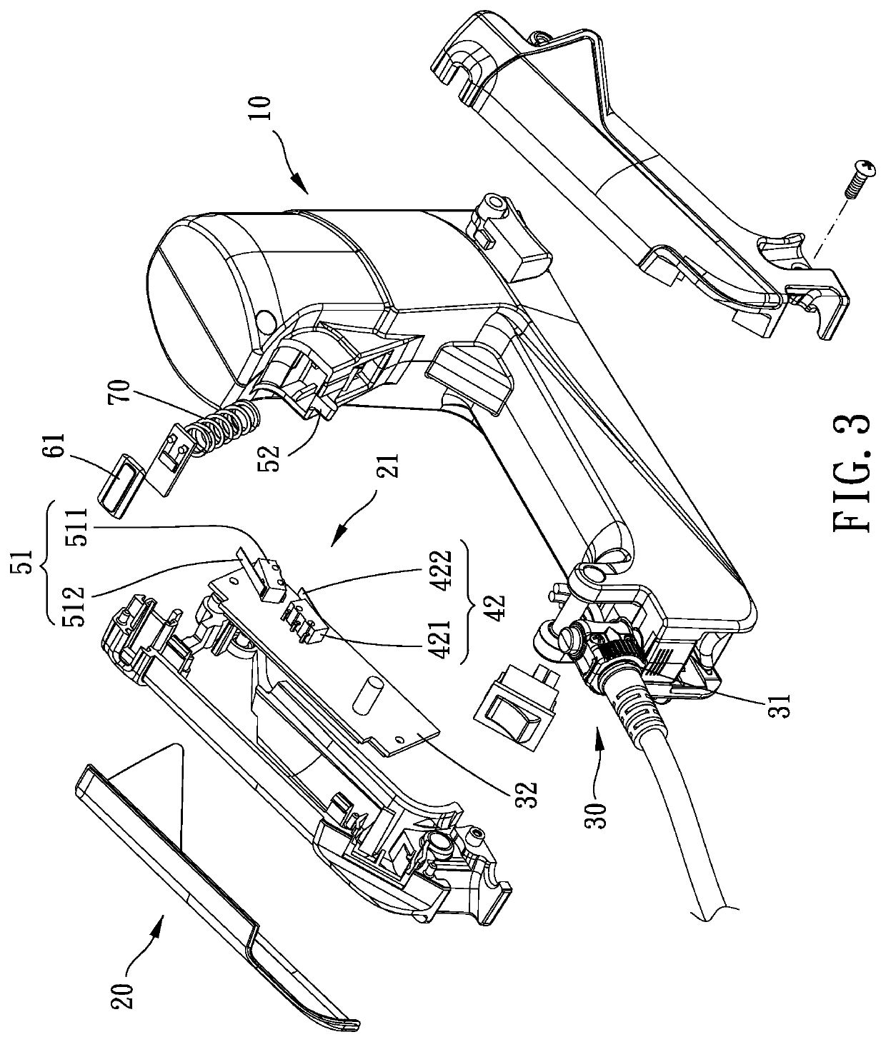
[0016]Please refer to FIG. 1 to FIG. 6, the electric stapler of the present invention includes a main body 10, a handle 20, a power mechanism 30, a striking assembly, and a safety mechanism.

[0017]The main body 10 has a receiving space 11 and a staple outlet 12. The receiving space 11 communicates the staple outlet 12. The receiving space 11 is adapted for receiving at least one staple. The handle 20 is connected to the main body 10 and has a moving portion 21 which is movable between an original position and an unlock position with respect to the main body 10. The moving portion 21 is normally at the original position. In the present embodiment, a spring 70 is biased between the main body 10 and the handle 20 to make the handle 20 at the original position normally. The power mechanism 30 is disposed on one of the main body 10 and the handle 20. The striking assembly includes a striking mechanism 41 and a trigger switch 42. The striking mechanism 41 is arranged in the receiving space...


PUM


Abstract

An electric stapler includes a main body, a handle, a striking assembly, and a safety mechanism between the main body and the handle. The handle is movable with respect to the main body between an original position and an unlock position. The striking assembly includes a striking mechanism for striking the staple out and a trigger switch on the handle for triggering the striking mechanism. The trigger switch has a strikable state and a locking state. When the handle is at the original position, the safety mechanism is at a locking mode to make the trigger switch at the locking state. When the handle is at the unlock position, the safety mechanism is at an unlock mode to make the trigger switch at the strikable state. An angle between the moving direction of the handle and the striking direction is smaller than 90 degrees.

Description

BACKGROUND OF THE INVENTIONField of the Invention[0001]The present invention relates to an electric stapler, more especially to an electric stapler having safety mechanism.Description of the Prior Art[0002]Normal staplers include mechanical staplers and electric staplers. The electric staplers are easier to strike the staple out than the mechanical staplers, but the force of striking of the electric staplers is also much higher than the mechanical staplers. Thus, the electric staplers are more dangerous.[0003]To improve the safety, safety mechanism is usually included in the electric stapler. A common safety mechanism is a two-stage trigger button. When the trigger button is pressed at the first stage, a resistance from the trigger button can inform the user that the striking mechanism has been unlocked. The user has to exert larger force to strike the staple out. Thus, accidentally striking is prevented. Another safety mechanism shown in patent TW 303772 has a safety button beside ...

Claims


Application Information

Patent Timeline
Patent Type & Authority Applications(United States)
IPC IPC(8): B25C5/15B25C5/02
CPCB25C5/15B25C5/0285
Inventor WANG, JING-LI
Owner APEX MFG
Why Eureka
Try Eureka