Automatic instrument device

An instrument and inner surface technology, applied in the field of automated instrumentation devices, can solve problems such as damage and accidental impact, and achieve the effects of convenient operation, improving service life and preventing damage.

Inactive Publication Date: 2020-12-08
西安安迈工业自动化技术有限公司
View PDF1 Cites 0 Cited by
  • Summary
  • Abstract
  • Description
  • Claims
  • Application Information

AI Technical Summary

Problems solved by technology

[0006] The purpose of the present invention is to solve the problem that the liquid level gauge in the prior art is exposed when it is installed and is easily damaged by accidental impact, and proposes an automatic instrument device

Method used


Image

  • Automatic instrument device
  • Automatic instrument device
  • Automatic instrument device

Examples


Embodiment 1

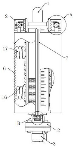
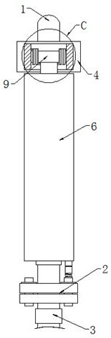
[0026] Example 1 as Figure 1-2 As shown, this automatic instrument device includes a liquid level gauge 1, a flange 2 and a drain valve 3, the flange 2 is located at the bottom of the liquid level gauge 1, the drain valve 3 is located at the lower end of the flange 2, and the upper end of the liquid level gauge 1 Both sides are fixed with connecting plates 4, and the other ends of the two connecting plates 4 are fixed with U-shaped plates 5, and both sides of the liquid level gauge 1 and below the two U-shaped plates 5 are equipped with U-shaped protective plates. Plate 6, the U-shaped protective plate 6 is set to effectively protect the liquid level gauge 1, the U-shaped protective plate 6 is wrapped and arranged on the outside of the liquid level gauge 1, and the front sides of the two U-shaped protective plates 6 are fixed with a vertical plate 7 , the bottoms of the two vertical plates 7 are fixedly provided with connecting blocks 8, the insides of the two connecting bloc...

Embodiment 2

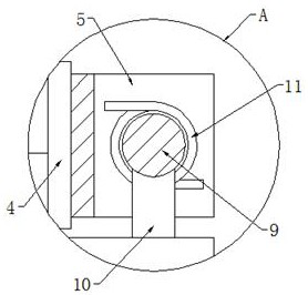
[0027] Embodiment 2 is on the basis of embodiment 1 such as image 3 and Figure 5 As shown, its elastic recovery mechanism includes a rotating rod 9, the two ends of the rotating rod 9 are fixedly connected with the two ends of the inner surface of the U-shaped plate 5 respectively, the bottom of the rotating rod 9 is fixedly provided with a support rod 10, and the bottom of the support rod 10 Fixedly connected with the top of the U-shaped protective plate 6, the two ends of the rotating rod 9 are sleeved with a torsion spring 11, and the two ends of the torsion spring 11 are fixedly connected with the inner surface of the U-shaped plate 5 and the support rod 10 respectively.

Embodiment 3

[0028] Embodiment 3 is such as on the basis of embodiment 1 Figure 4 As shown, its connection mechanism includes a pull plate 12 and an insertion rod 13, the bottom of the left connecting block 8 is provided with a mounting groove, the bottom of the right connecting block 8 is provided with a slot, and the bottom of the mounting groove is fixed with a telescopic rod 14 and the first spring 15, the other end of the telescopic rod 14 and the first spring 15 is fixedly connected with the top left side of the pull plate 12, the bottom of the insertion rod 13 is fixedly connected with the top right side of the pull plate 12, and the top is connected with the slot Plugging, the first spring 15 is socketed with the telescopic rod 14, and the socket is connected with the plugging rod to connect the two U-shaped protective plates 6 .


PUM


Abstract

The invention relates to the technical field of automatic instruments, and discloses an automatic instrument device which comprises a liquid level meter, a flange and a blow-down valve, the flange islocated at the bottom of the liquid level meter, the blow-down valve is located at the lower end of the flange, connecting plates are fixedly arranged on the two sides of the upper end of the liquid level meter, and U-shaped plates are fixedly arranged at the other ends of the two connecting plates. U-shaped protection plates are arranged on the two sides of the liquid level meter and located below the two U-shaped plates, the U-shaped protection plates are arranged on the outer side of the liquid level meter in a wrapping mode, vertical plates are fixedly arranged on the front sides of the two U-shaped protection plates, connecting blocks are fixedly arranged at the bottoms of the two vertical plates, connecting mechanisms are arranged in the two connecting blocks, and elastic return mechanisms are arranged in the two U-shaped plates. Damping mechanisms are arranged on the sides, away from the liquid level meters, in the two U-shaped protection plates. According to the automatic instrument device, the liquid level meter can be effectively wrapped and protected.

Description

technical field [0001] The invention relates to the technical field of automatic instruments, in particular to an automatic instrument device. Background technique [0002] An automatic instrument is an automatic technical tool composed of several automatic components and has relatively complete functions, and a liquid level gauge, as an instrument used to detect the liquid level inside a container, is also a kind of automatic instrument. [0003] Among them, the patent number CN202814500U discloses a liquid level gauge. When the liquid level gauge is in use, according to the principle of the connecting pipe, the liquid level height in the measured container is consistent with the liquid level height in the measuring cylinder. The upper and lower positions of the measured container reflect the height of the liquid level in the measured container. At the same time, when checking the accuracy, the first control valve can be closed first, and the second control valve can be ope...

Claims


Application Information

Patent Timeline
IPC IPC(8): G01F23/02G01D11/30G01D11/24G01D11/10
CPCG01D11/10G01D11/24G01D11/30G01F23/02
Inventor 史葳
Owner 西安安迈工业自动化技术有限公司
Why Eureka
Try Eureka