
Image coding method and device using deblocking filtering

a filtering and image coding technology, applied in the field of image coding technology, can solve the problems of increased achieve the effects of reducing transmission costs and storage costs, reducing transmission costs, and improving image quality of image/video

Active Publication Date: 2021-10-14
LG ELECTRONICS INC
View PDF0 Cites 2 Cited by
  • Summary
  • Abstract
  • Description
  • Claims
  • Application Information

AI Technical Summary

Benefits of technology

The present patent aims to provide a method and device for improving image and video coding efficiency and quality. It does this by enhancing image compression efficiency and improving image quality through various means such as boundary strength design and deblocking filter process. These improvements can lead to better subjective and objective image quality.

Problems solved by technology

Accordingly, if image data is transmitted using a medium, such as the existing wired or wireless wideband line, or image and video data are stored using the existing storage medium, transmission costs and storage costs are increased.

Method used


Image

  • Image coding method and device using deblocking filtering
  • Image coding method and device using deblocking filtering
  • Image coding method and device using deblocking filtering

Examples


Embodiment Construction

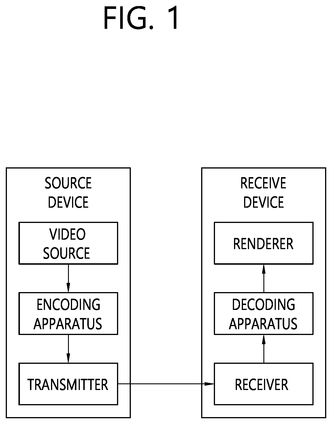
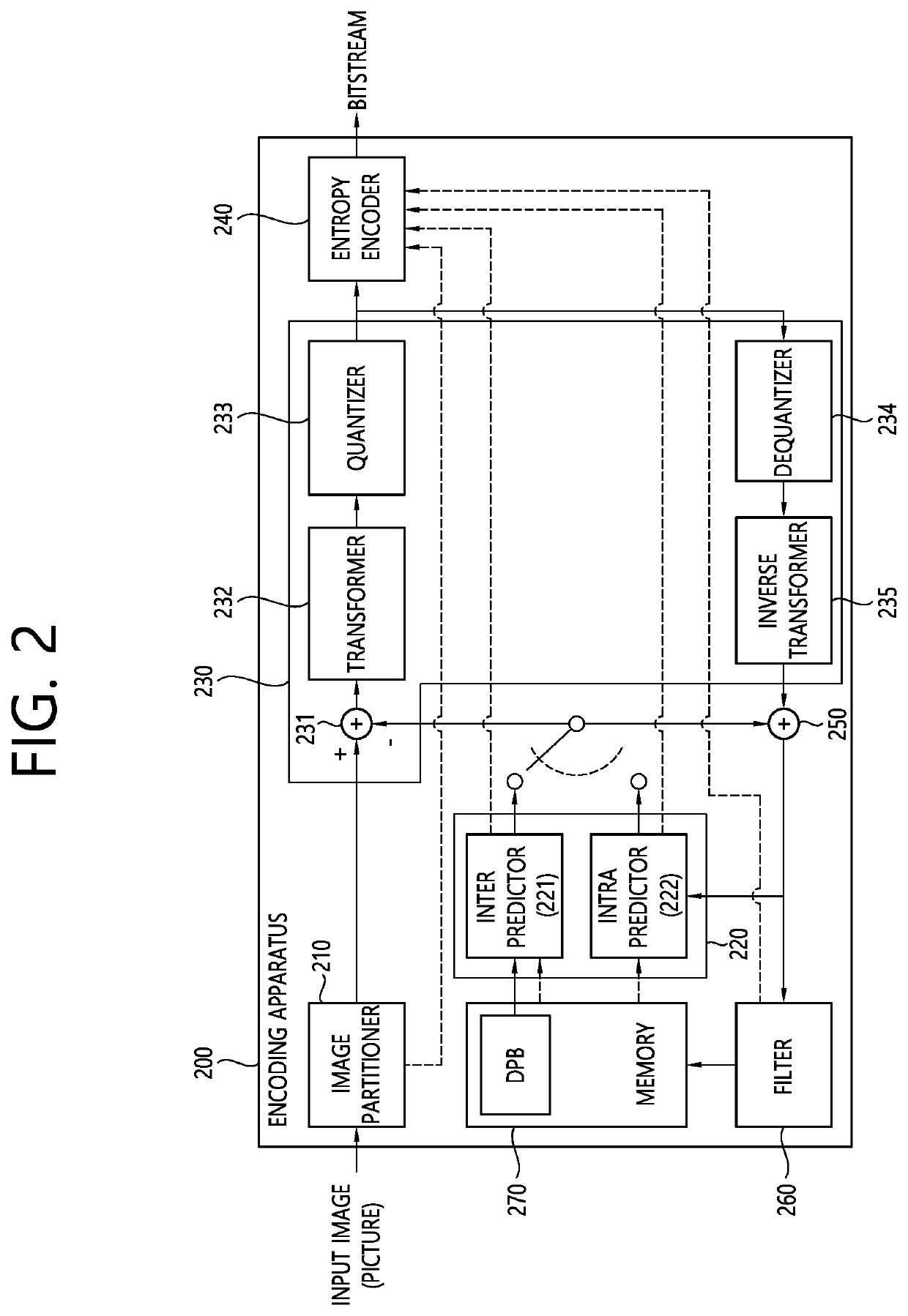
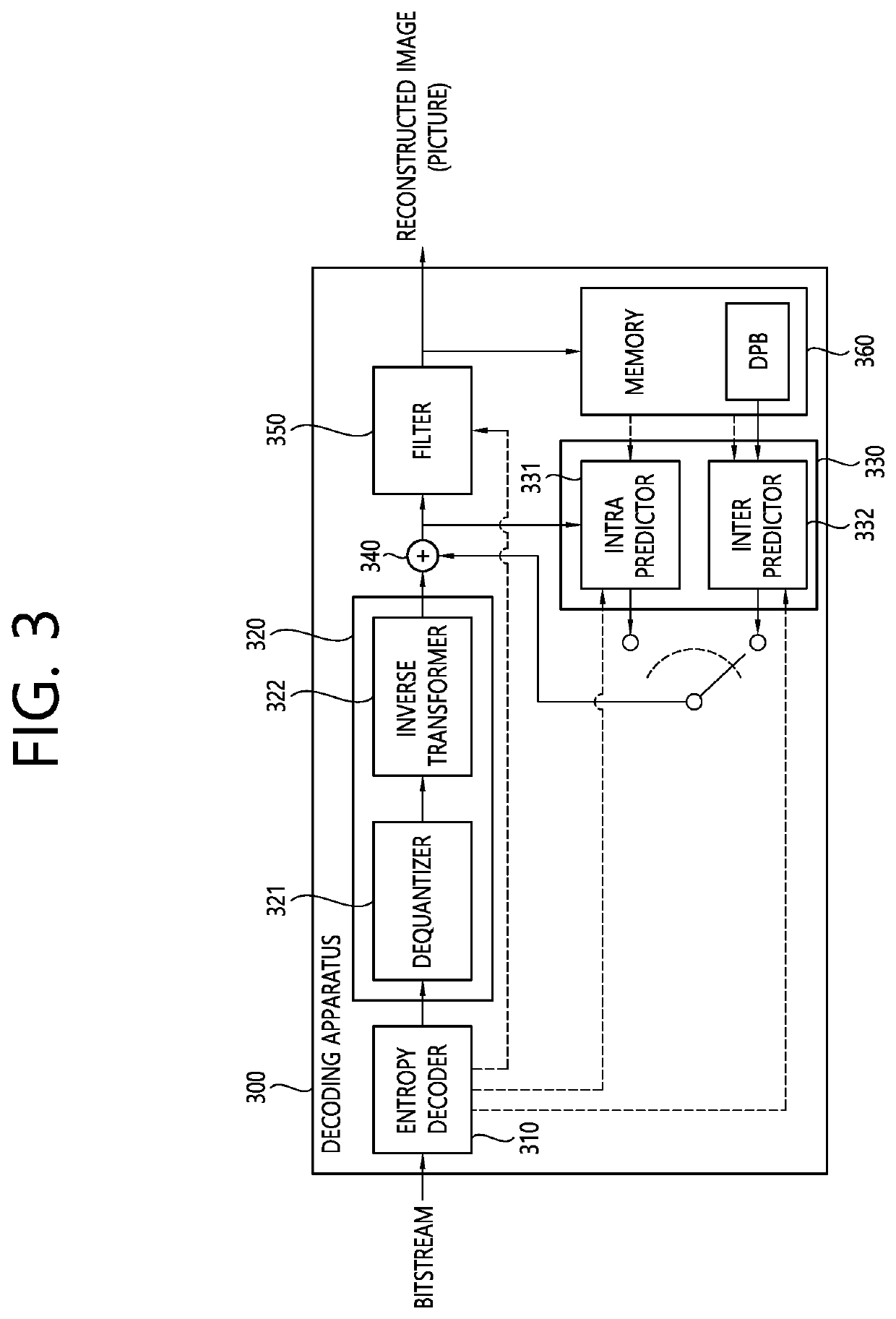
[0023]This document may be modified in various ways and may have various embodiments, and specific embodiments will be illustrated in the drawings and described in detail. However, this does not intend to limit this document to the specific embodiments. Terms commonly used in this specification are used to describe a specific embodiment and is not used to limit the technical spirit of this document. An expression of the singular number includes plural expressions unless evidently expressed otherwise in the context. A term, such as “include” or “have” in this specification, should be understood to indicate the existence of a characteristic, number, step, operation, element, part, or a combination of them described in the specification and not to exclude the existence or the possibility of the addition of one or more other characteristics, numbers, steps, operations, elements, parts or a combination of them.

[0024]Meanwhile, elements in the drawings described in this document are indep...


PUM


Abstract

A method by which a decoding device decodes an image, according to the present document, comprises the steps of: generating a restoration picture on the basis of prediction samples of a coding block; deriving a boundary strength (BS) for a boundary of the coding block in the restoration picture; performing deblocking filtering on the boundary of the coding block on the basis of the boundary strength; and deriving a modified restoration picture for the restoration picture on the basis of the deblocking filtering, wherein the boundary strength is derived on the basis of a prediction mode of a first block and a second block that are adjacent to the boundary of the coding block, and the prediction mode of the first block or the second block is derived on the basis of whether the prediction mode of the first block or the second block is a current picture referencing (CPR) mode to be coded in reference to a current picture.

Description

BACKGROUND OF THE DISCLOSUREField of the Disclosure[0001]The present document relates to an image coding technology, and more specifically, to an image coding method and apparatus using a deblocking filter process.Related Art[0002]The demands for high-resolution and high-quality images and video, such as an ultra high definition (UHD) image and video of 4K or 8K or more, are recently increasing in various fields. As image and video data become high resolution and high quality, the amount of information or the number of bits that is relatively transmitted is increased compared to the existing image and video data. Accordingly, if image data is transmitted using a medium, such as the existing wired or wireless wideband line, or image and video data are stored using the existing storage medium, transmission costs and storage costs are increased.[0003]Furthermore, interests and demands for immersive media, such as virtual reality (VR), artificial reality (AR) content or a hologram, are ...

Claims


Application Information

Patent Timeline
Patent Type & Authority Applications(United States)
IPC IPC(8): H04N19/82H04N19/117H04N19/176H04N19/85
CPCH04N19/82H04N19/85H04N19/176H04N19/117H04N19/86H04N19/105H04N19/14H04N19/132H04N19/42H04N19/159H04N19/157
Inventor JANG, HYEONGMOONNAM, JUNGHAK
Owner LG ELECTRONICS INC
Learn More