
Heat exchanger

a technology of heat exchanger and heat exchanger body, which is applied in the direction of indirect heat exchanger, light and heating apparatus, stationary plate conduit assembly, etc., can solve the problems of deterioration of system performance, high cost, and improved design, and achieves low cost, effective control, and easy manufacture. the effect of installation and maintenan

Active Publication Date: 2021-10-14
CARRIER CORP
View PDF0 Cites 0 Cited by
  • Summary
  • Abstract
  • Description
  • Claims
  • Application Information

AI Technical Summary

Benefits of technology

The present disclosure provides a heat exchanger that overcomes various problems of the prior art, such as high cost, difficulty in maintenance, and limited control of LCO. The heat exchanger has an optimized structure, low cost, and can effectively control LCO, leading to a compact design. Its use improves the overall performance, safety, and reliability of the system, avoiding adverse effects on other components associated with the heat exchanger.

Problems solved by technology

Due to the limitations such as liquid carryover (LCO), such heat exchangers are usually conservative in design, so as to avoid problems such as expensive improved design and deteriorated system performance caused by the LCO.

Method used


Image

  • Heat exchanger
  • Heat exchanger
  • Heat exchanger

Examples


Embodiment Construction

[0029]Firstly, it is noted that the structural components, characteristics, and advantages of the heat exchanger of the present disclosure will be specifically described below by way of example. However, all the description is only for illustration, and does not limit the present disclosure in any way. Herein, the technical terms “first” and “second” are only used for the purpose of distinguishing the expressions, and are not intended to indicate their order and relative importance. The technical term “substantially” is intended to include non-substantive errors associated with the measurement of a specific amount (for example, it may include a range of ±8%, ±5%, or ±2% of a given value), and the technical terms “upper”, “lower”, “top”, “bottom”, “inner”, “outer”, “left”, “right” and derivatives thereof should be related to the orientations in the drawings; unless explicitly indicated otherwise, the present disclosure can take a variety of alternative orientations.

[0030]In addition,...


PUM


Abstract

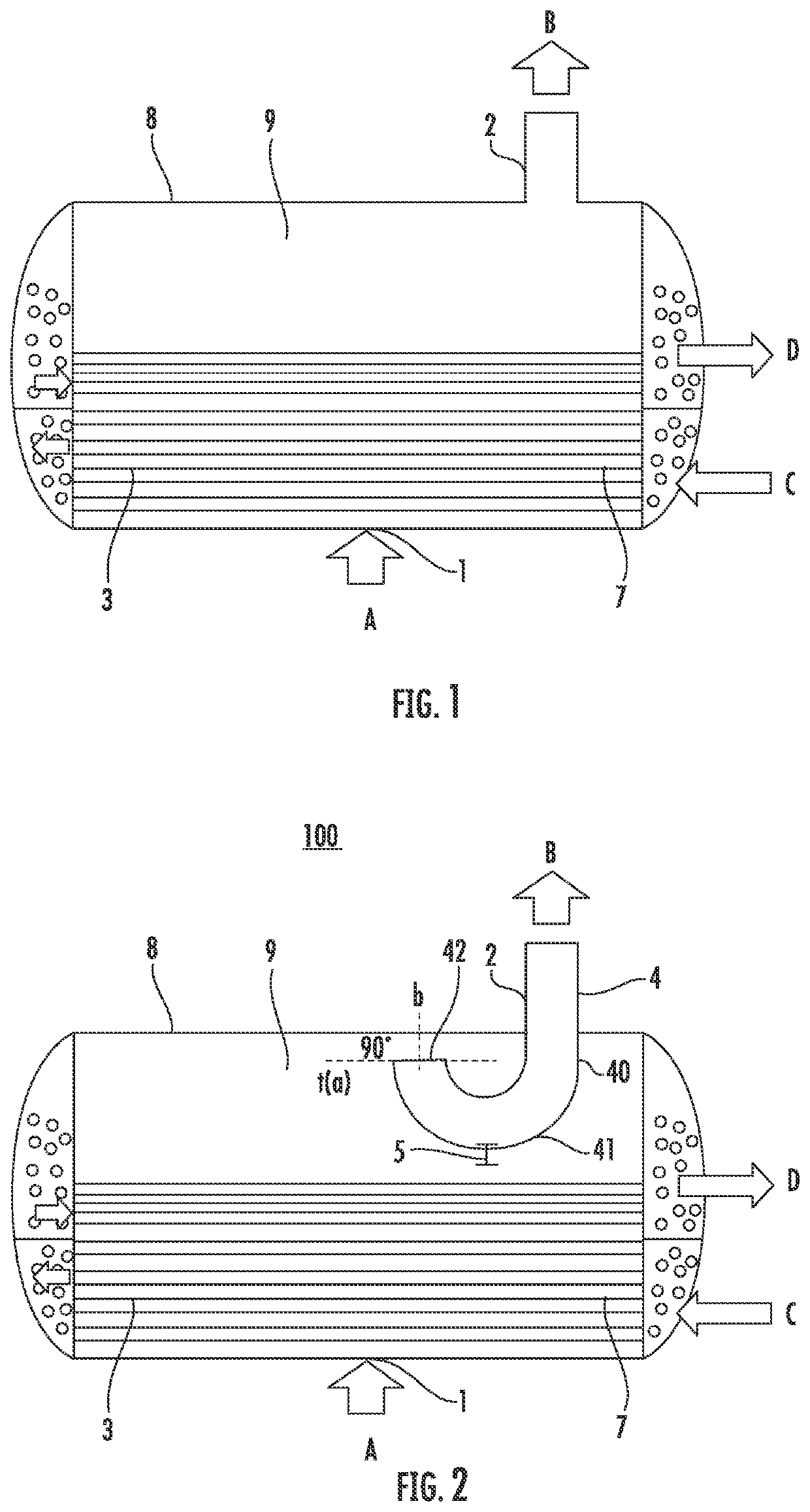
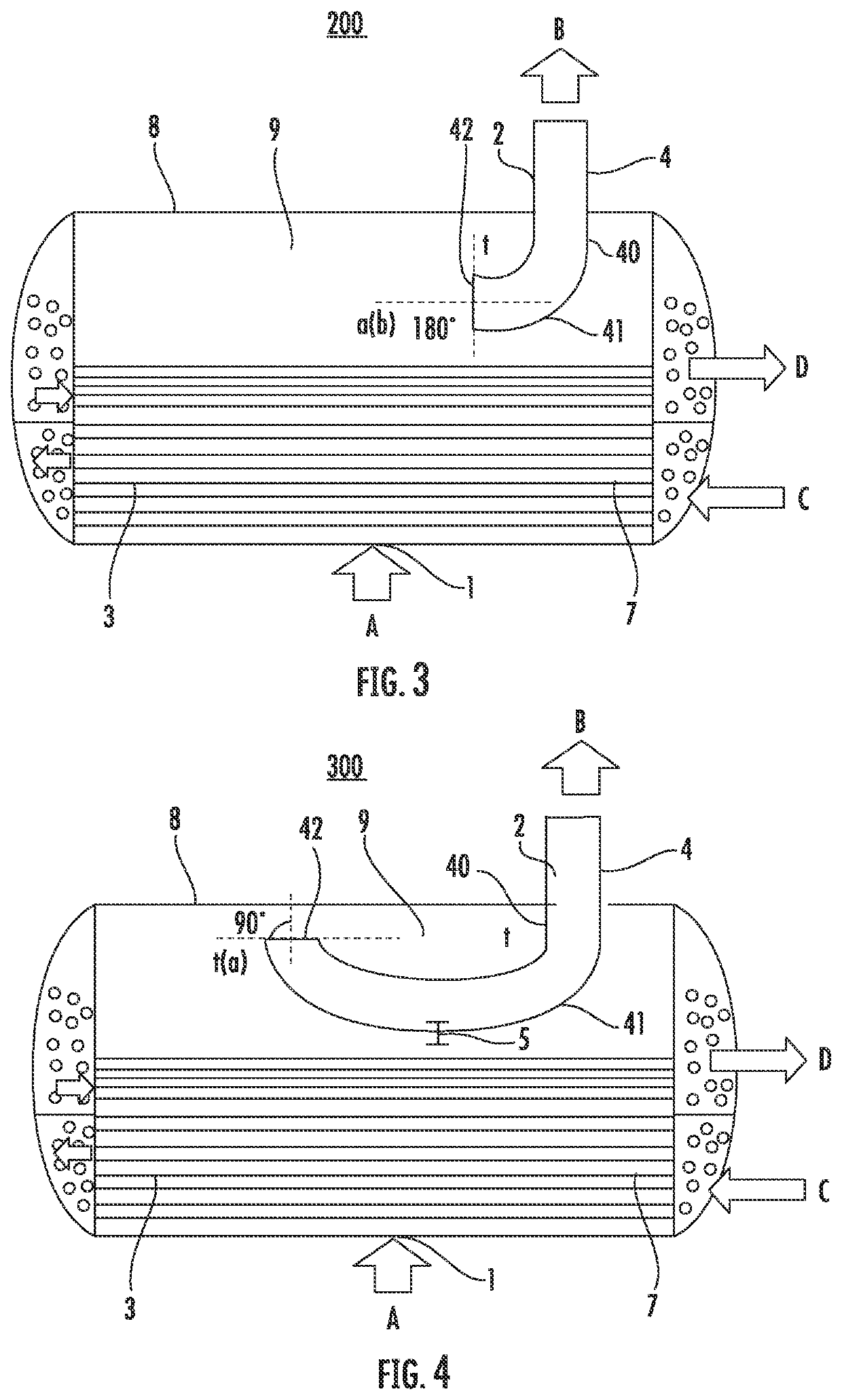
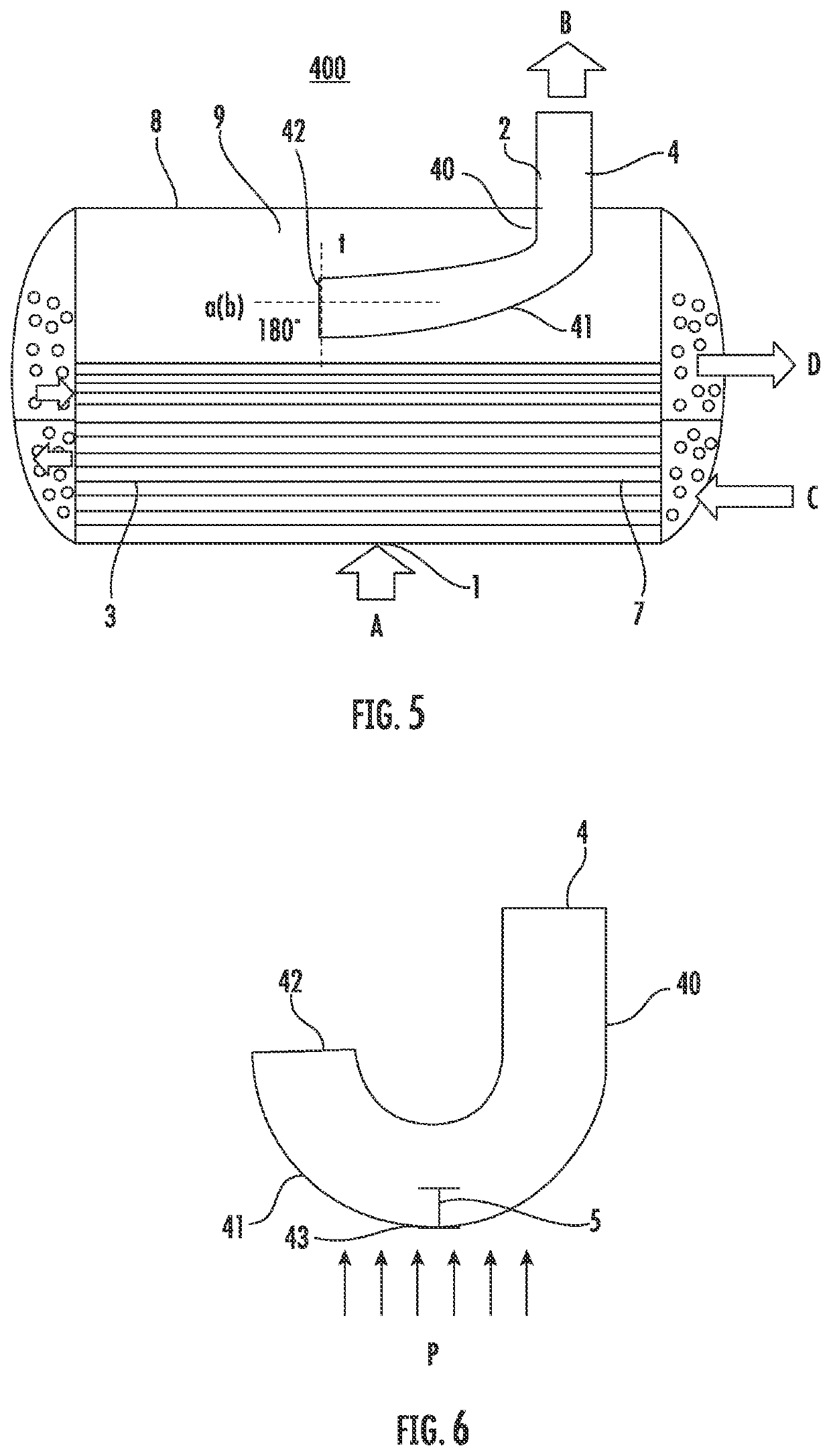
The disclosure relates to a heat exchanger. The heat exchanger includes a shell and heat exchange tube bundles located in the shell, the shell has an inlet and an outlet, and a refrigerant flows in through the inlet, exchanges heat with a fluid in the heat exchange tube bundles, and then flows out from the outlet, and the outlet is provided with an extension section that extends into an interior of the shell and has a receiving portion configured to receive at least a part of a liquid in the refrigerant flowing toward the outlet after heat exchange. The disclosure is easy to manufacture, install and maintain, and has a low cost. By optimizing the structure of an outlet pipeline of the heat exchanger, the influence of liquid carryover can be effectively controlled, and the overall performance, safety and reliability of the system can be enhanced.

Description

CROSS-REFERENCE TO RELATED APPLICATIONS[0001]This application claims the benefit of Chinese Application No. CN202010274124.4 filed Apr. 9, 2020, the disclosure of which is incorporated herein by reference in its entirety.BACKGROUND[0002]The present disclosure relates to the technical field of heat exchange, and in particular to a heat exchanger.[0003]Various types of heat exchange devices, apparatuses or systems have been provided in the prior art, which have been widely used in many industrial fields, places, etc., and can bring great convenience. However, these existing heat exchange devices, apparatuses or systems still have some drawbacks and shortcomings in aspects such as structural configuration, heat exchange effect, work performance, manufacturing, installation, and maintenance, and can be further improved and optimized.[0004]For example, FIG. 1 shows a side view of the structure of an existing flooded evaporator. Most of shells of such flooded evaporators are cylindrical a...

Claims


Application Information

Patent Timeline
Patent Type & Authority Applications(United States)
IPC IPC(8): F25B39/02F28D9/00F28D21/00
CPCF25B39/028F28F9/005F28D21/0017F28D9/0043F28D7/16F28F9/02F28D2021/0071F25B2339/0242F25B39/02
Inventor ZHANG, WEI
Owner CARRIER CORP
Learn More