
Steering control method and steering control device

a technology of steering control and control method, which is applied in the direction of steering control, steering parts, vehicle components, etc., can solve the problems of affecting the smooth steering control of the automatic steering control, and achieve the effect of improving the steering feel

Active Publication Date: 2021-10-07
NISSAN MOTOR CO LTD
View PDF4 Cites 5 Cited by
  • Summary
  • Abstract
  • Description
  • Claims
  • Application Information

AI Technical Summary

Benefits of technology

The invention aims to improve the steering feel in a vehicle with a steer-by-wire steering mechanism. By applying a steering reaction force to the steering wheel, the steering angle fluctuations caused by the actuator are reduced, allowing for smoother steering control.

Problems solved by technology

However, when the steering angle of the steering wheel is controlled by means of automatic steering control in order to control the steered wheels in accordance with the steering angle of the steering wheel, there are cases in which the steering angle fluctuates due to the steering reaction force generated by the actuator, thereby hindering the smooth steering controlled by the automatic steering control.

Method used


Image

  • Steering control method and steering control device
  • Steering control method and steering control device
  • Steering control method and steering control device

Examples


Embodiment Construction

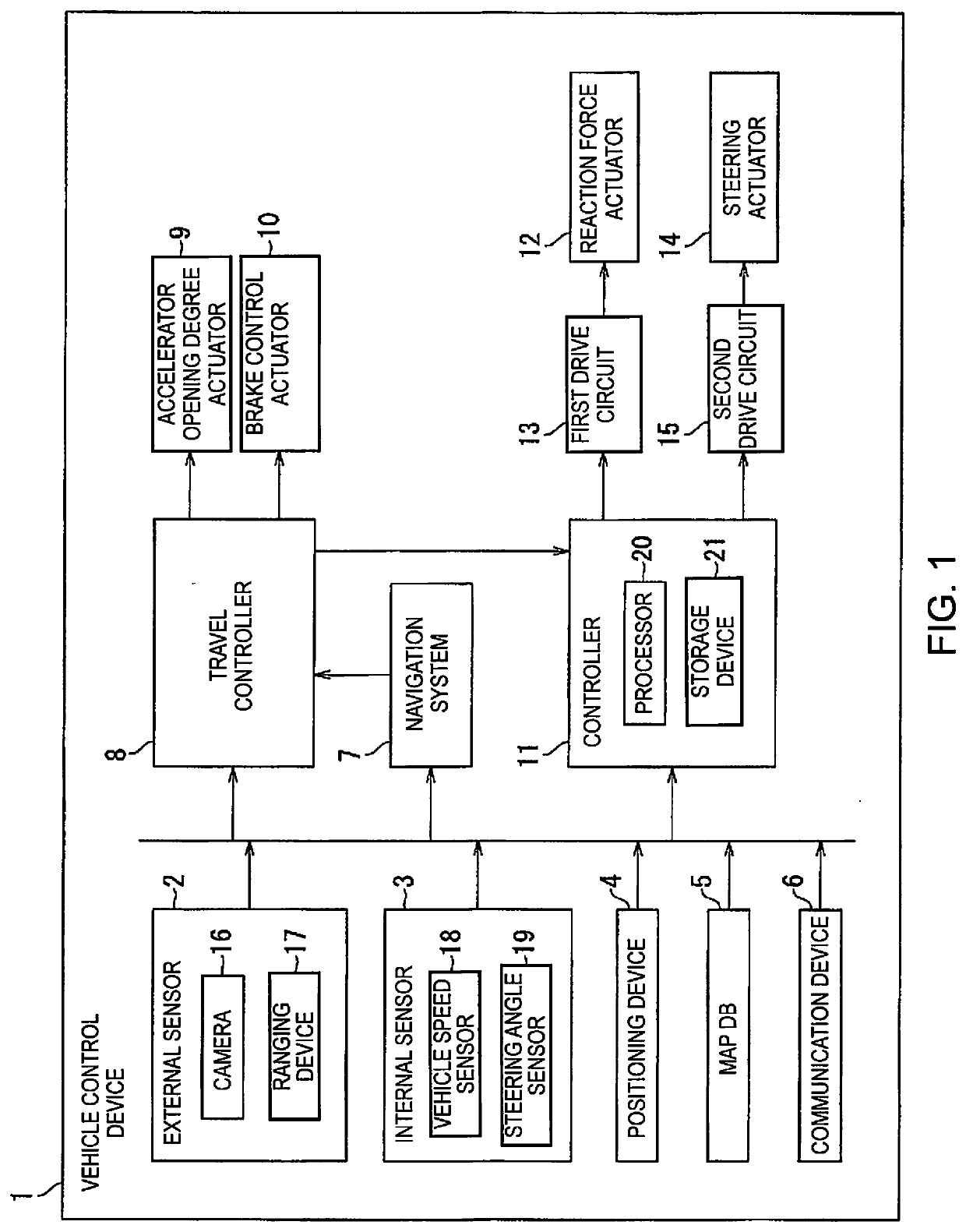
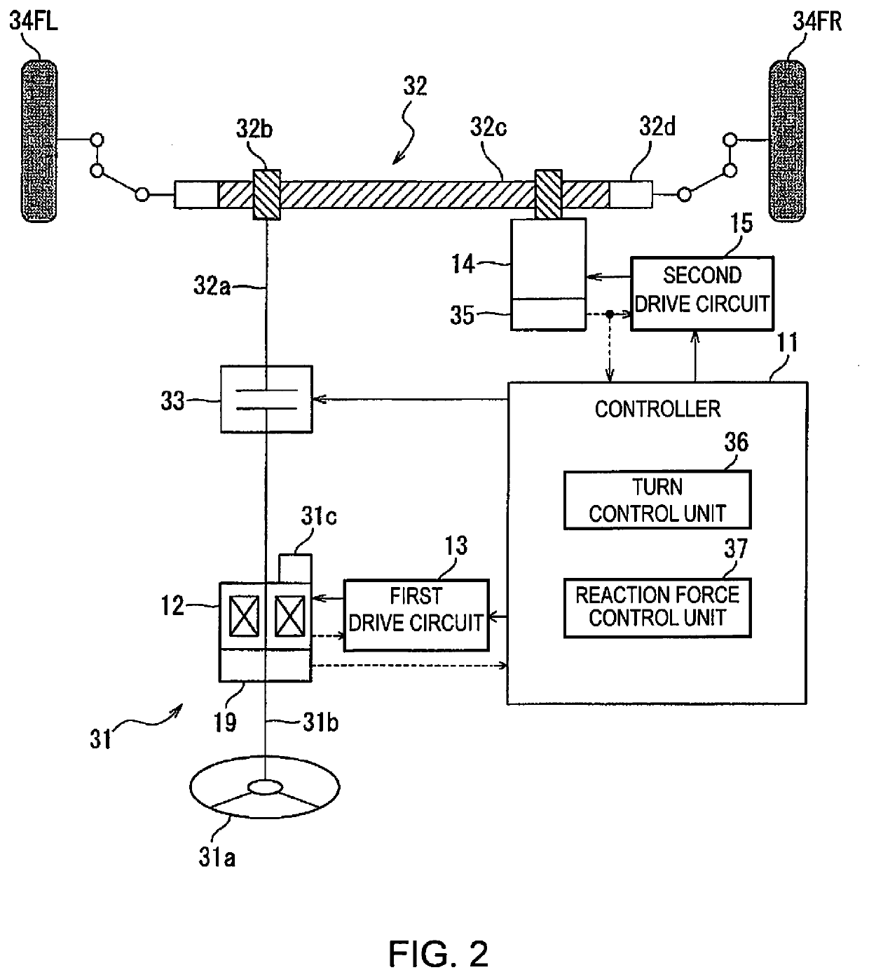
[0018]An embodiment of the present invention is described below with reference to the drawings. Reference is made to FIG. 1. A vehicle equipped with a vehicle control device 1 (hereinafter referred to as “host vehicle”) is provided with a steer-by-wire steering mechanism in which the steering wheel and the steered wheels are mechanically separated. The vehicle control device 1 controls the turning angle of the steered wheels and the steering reaction force that is applied to the steering wheel.

[0019]In addition, the vehicle control device 1 carries out autonomous driving control, wherein the host vehicle is automatically driven without the involvement of a driver, as well as driving assistance control, wherein a driver is assisted in the driving of the host vehicle. The driving assistance control includes, for example, lane-keeping control, preceding vehicle following control, automatic braking control, cruise control, etc.

[0020]The vehicle control device 1 comprises an external sen...


PUM


Abstract

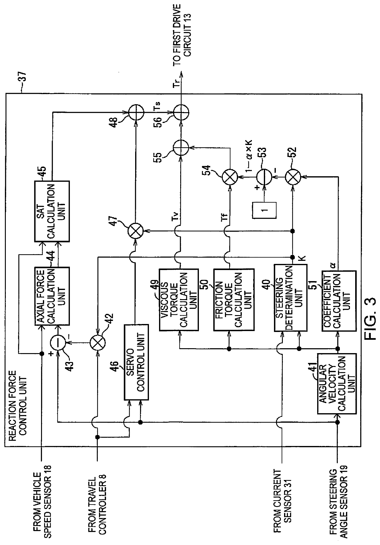
A steering control method controls the steering of a vehicle having a steer-by-wire steering mechanism. A steering reaction force is set that includes a restoration component for restoring a steering angle of the steering wheel to a reference angle, a viscous component corresponding to a steering angular velocity of the steering wheel, and a friction component corresponding to the steering angular velocity. An actuator is controlled to apply a rotational torque to the steering wheel for generating the steering reaction force. A turning angle of the steered wheel is controlled in accordance with the steering angle. A target travel path is set upon determining the driver is not operating the steering wheel. The actuator is controlled such that the steering angle becomes a target steering angle for causing the vehicle to travel along the target travel path to suppress the friction component of the steering reaction force.

Description

CROSS-REFERENCE TO RELATED APPLICATIONS[0001]This application is a U.S. national stage application of International Application No. PCT / JP2018 / 029791, filed on Aug. 8, 2018.BACKGROUNDTechnical Field[0002]The present invention relates to a steering control method and a steering control device.Background Information[0003]Japanese Laid-Open Patent Application No. 2007-137287 (Patent Document 1) discloses a steering device for application of a target reaction force torque, calculated by the addition of a friction torque that corresponds to the steering angular velocity, a viscous torque that corresponds to the steering angular velocity, and a self-aligning torque. A prescribed number of pulse signals output from a steering angle sensor are cleared to set the friction torque to “0,” in order to eliminate fluctuations caused by minute vibrations of the steering wheel, and to apply a target reaction force torque that changes smoothly.SUMMARY[0004]In a vehicle that employs a steer-by-wire s...

Claims


Application Information

Patent Timeline
Patent Type & Authority Applications(United States)
IPC IPC(8): B62D6/00
CPCB62D6/008B62D6/002B62D15/025
Inventor SUZUKI, TAKU
Owner NISSAN MOTOR CO LTD
Learn More