
Power supply system with automatic transfer switches

a technology of power supply system and automatic transfer switch, which is applied in the direction of dc source parallel operation, emergency power supply arrangement, pulse technique, etc., can solve the problems of poor reliability at high currents, inability to withstand instantaneous large currents, and slow switching time, so as to improve power supply quality and reliability, shorten the switching time, and improve the effect of switching control

Active Publication Date: 2021-09-30
DELTA ELECTRONICS INC
View PDF0 Cites 0 Cited by
  • Summary
  • Abstract
  • Description
  • Claims
  • Application Information

AI Technical Summary

Benefits of technology

The patent text describes a power supply system that uses automatic transfer switches and controllable semiconductor switches to improve power supply quality and reliability. These switches can turn off when large currents flow through, and they have shorter switching time, which allows for more accurate switching control. Overall, this system can provide better performance and higher efficiency for power supply applications.

Problems solved by technology

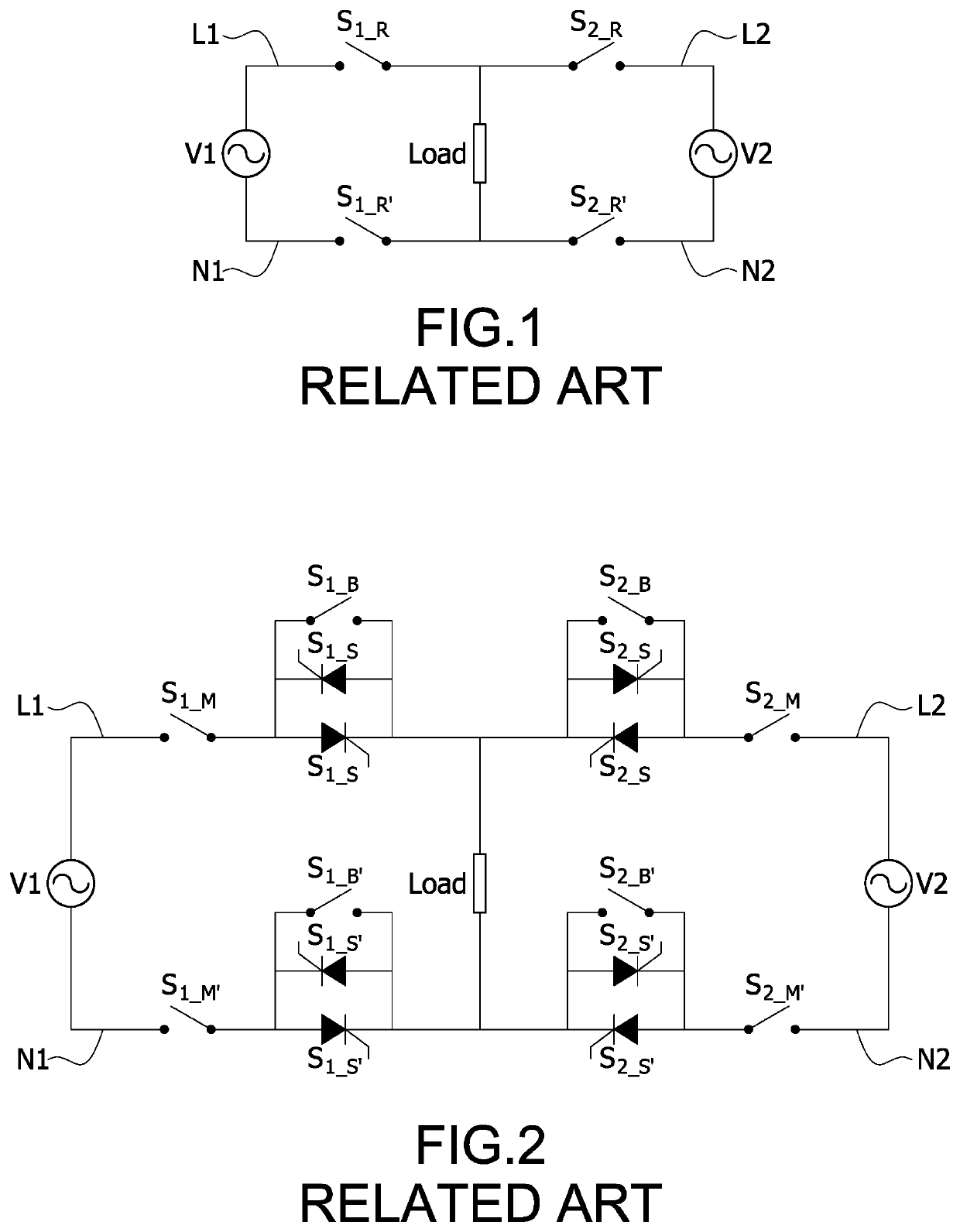
However, during the process of switching the power sources, some issues may occur due to the mechanical characteristics of the relay, such as slow switching time and unable to withstand instantaneous large currents (poor reliability at high currents).
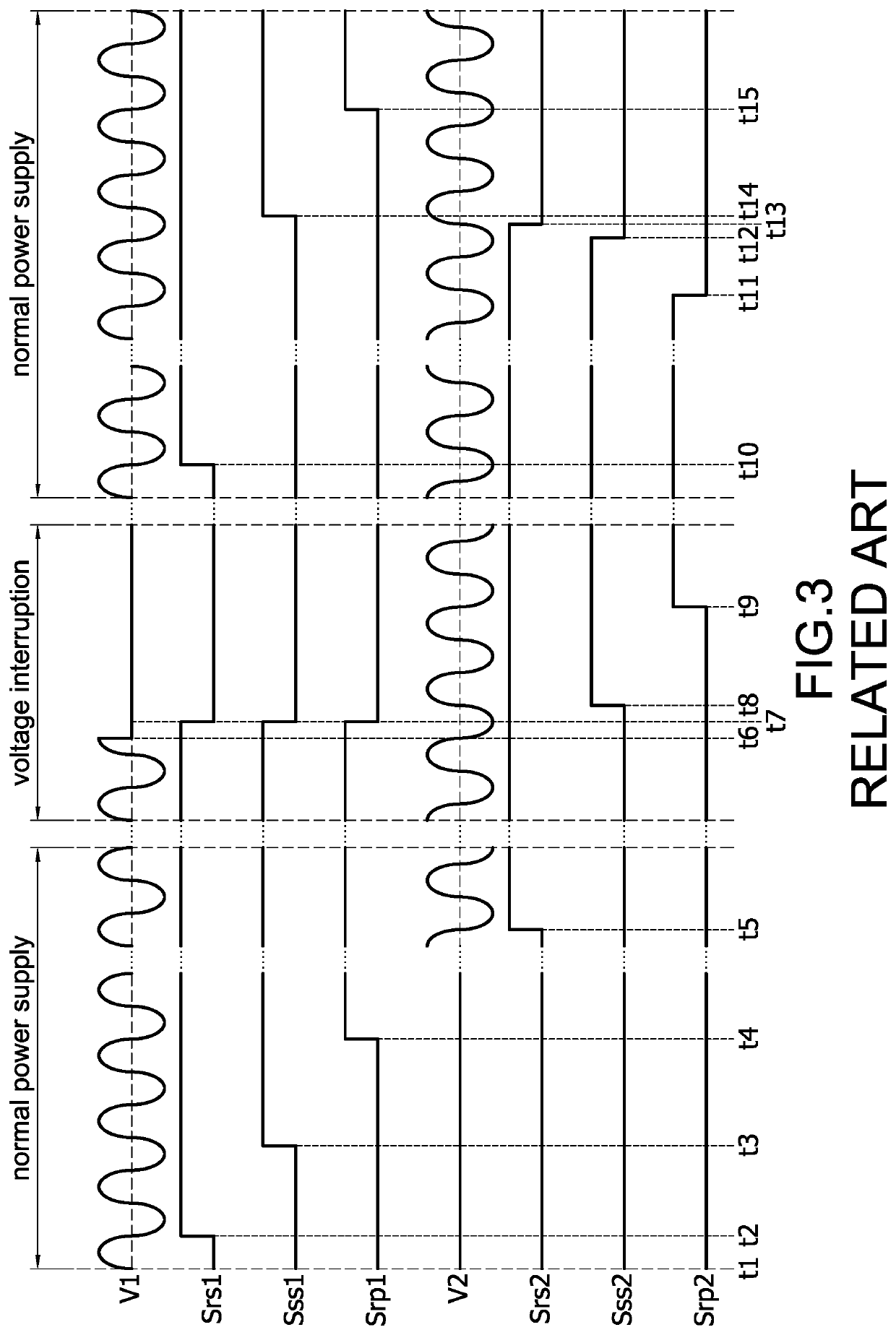
Furthermore, after switching for many times, the relay switches may fail to open or close, which may cause switching failures or mismatches of switching sequence between the main power source V1 and the backup power source V2.
However, such technology of automatic transfer switches is not only limited to the application of voltage interruption, but also can be applied to any abnormality or failure of the main power source, such as voltage sags or surges.
However, in the process of disconnecting the power source of the circuit in FIG. 2, due to the characteristic of the SCR that it cannot be turned off by external control signals, the circuit still needs to be cut off by the relay switches.
Therefore, the switching issues may still occur because of the above-mentioned characteristics of the relay switches, such as slow switching time and poor reliability at large currents.

Method used


Image

  • Power supply system with automatic transfer switches
  • Power supply system with automatic transfer switches
  • Power supply system with automatic transfer switches

Examples


Embodiment Construction

[0022]Please refer to FIG. 4. The power supply system with automatic transfer switches of the present disclosure is used to uninterruptedly supply power to a load. The power supply system with automatic transfer switches includes two first switch apparatuses 10,10′, two second switch apparatuses 20,20′, and a control unit 30. The two first switch apparatuses 10,10′ are respectively coupled to a first point and a second point of a first power source V1, for example, a main power source V1, and will be presented in terms of “main power source switch apparatus” in the following contents. The two second switch apparatuses 20,20′ are respectively coupled to a first point and a second point of a second power source V2, for example, a backup power source V2, and will be presented in terms of “backup power source switch apparatus” in the following contents. When the main power source V1 and the backup power source V2 are single-phase AC power sources, the first point of the main power sourc...


PUM


Abstract

A power supply system for automatic transfer switch applications comprises two first switch apparatuses, two second switch apparatuses, and a control unit. Each first switch apparatus comprises a first relay switch and a first switch assembly. The first switch assembly comprises a first bypass switch, a first semi-controllable switch, and a first fully-controllable switch. Each second switch apparatus comprises a second relay switch and a second switch assembly. The second switch assembly comprises a second bypass switch, a second semi-controllable switch, and a second fully-controllable switch. The control unit controls the two first switch apparatuses and the two switch apparatuses to uninterruptedly supply power to a load.

Description

BACKGROUNDTechnical Field[0001]The present disclosure relates to a power supply system, and more particularly to a power supply system with automatic transfer switches.Description of Related Art[0002]Automatic transfer switch (ATS) is a power circuit switch, which is used to switch power supply circuits between a main power source and a backup power source so as to uninterruptedly supply power to a load. When the main power source is insufficient, interrupted or abnormal, the automatic transfer switch will automatically switch the power supply circuit to the backup power source, so that the backup power source can alternatively continue to provide stable power to the load, which ensures the equipment of the load being able to continue to operate and avoid further risks of property or human damage and financial losses caused by the power failure condition.[0003]Please refer to FIG. 1. The power supply system has a dual power source circuit structure, and the two power sources V1 and ...

Claims


Application Information

Patent Timeline
Patent Type & Authority Applications(United States)
IPC IPC(8): H02J9/06H02J1/10H03K17/60H03K17/687
CPCH02J9/061H02J1/10H03K17/687H02J9/068H03K17/60H02J9/062H02J9/06H02J9/04
Inventor WU, CHIH-MINGMAI, CHI-MINGZENG, YU-RUEI
Owner DELTA ELECTRONICS INC
Learn More