Gas chromatograph

a technology of gas chromatograph and chromatograph, which is applied in the field of gas chromatograph, can solve the problems of inconvenient supply of outside air to the main body, impaired accuracy of temperature control of the separation column,

Pending Publication Date: 2021-09-30
SHIMADZU CORP
View PDF2 Cites 0 Cited by
  • Summary
  • Abstract
  • Description
  • Claims
  • Application Information

AI Technical Summary

Benefits of technology

[0007]The present invention has been made in view of the above problem, and an object of the present invention is to suppress the influence of heat from the interface part on the temperature control of the separation column and also to suppress the influence of room temperature fluctuation outside the main body.
[0009]The gas chromatograph according to the present invention includes, in addition to the first fan for supplying air into the column cartridge, the second fan for blowing air to the outer surface of the column cartridge to cool the column cartridge. Accordingly, heat transmitted from the interface part to the outer surface of the column cartridge is removed by the air blown by the second fan, and the influence of the heat from the interface part on the temperature control of the separation column is suppressed. As a result, it is no longer necessary to supply air from the outside of the main body into the column cartridge during the analysis, and, by stopping the operation of the first fan during the analysis, the influence of the room temperature fluctuation outside the main body on the temperature control of the separation column can also be suppressed.

Problems solved by technology

However, if outside air of the main body is supplied into the column cartridge during analysis, the accuracy of temperature control of the separation column may be impaired due to the influence of room temperature fluctuation.
Therefore, it is not desirable to supply outside air of the main body into the column cartridge during analysis.

Method used


Image

  • Gas chromatograph
  • Gas chromatograph

Examples


Embodiment Construction

[0012]Hereinafter, an embodiment of the gas chromatograph according to the present invention will be described with reference to the accompanying drawings.

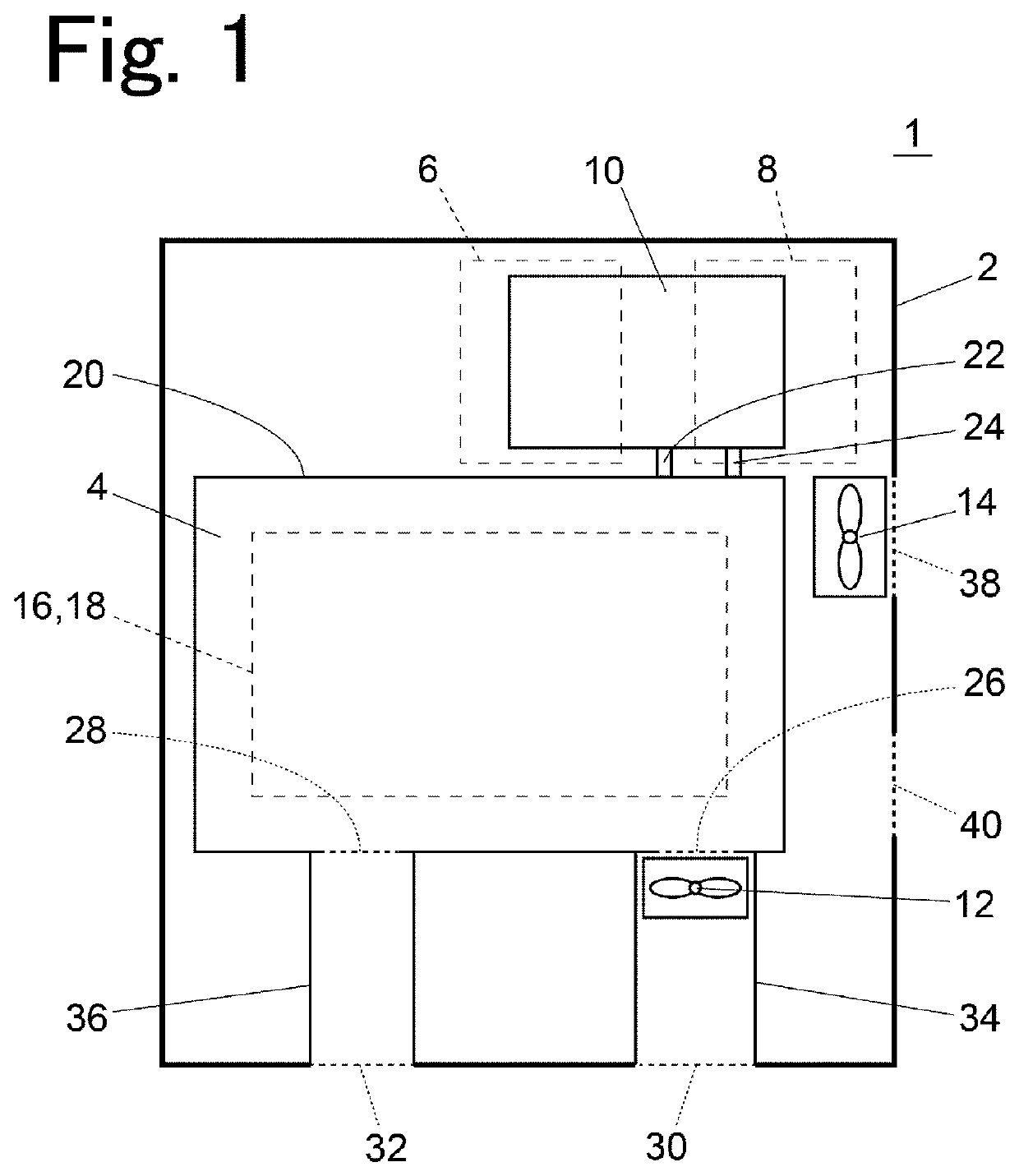
[0013]FIG. 1 is a schematic view of an internal configuration of a main body 2 of a gas chromatograph 1 as viewed from above.

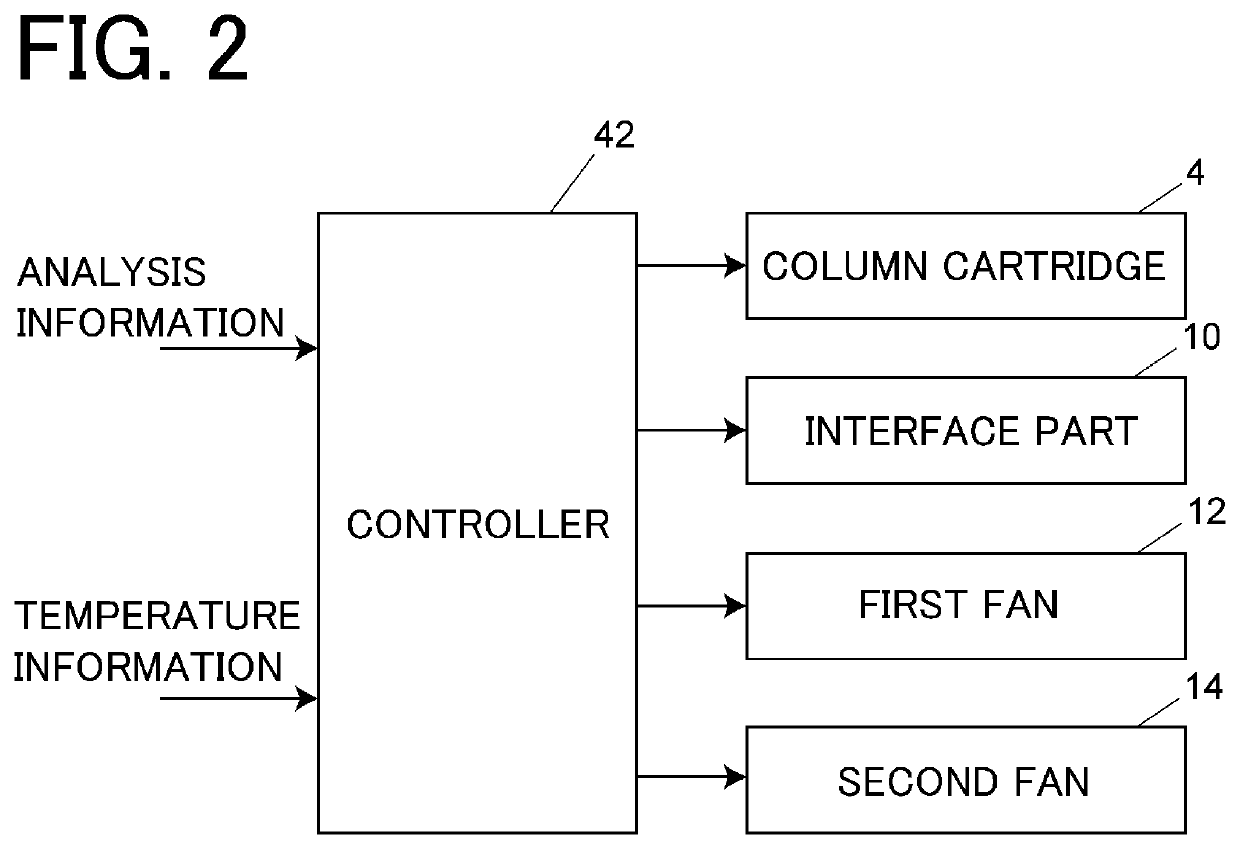
[0014]The main body 2 of the gas chromatograph 1 has internal space, and a column cartridge 4, an interface part 10, a first fan 12, and a second fan 14 are disposed in the internal space. Further, a sample gas supplier 6 and a detector 8 are attached to the main body 2.

[0015]In the column cartridge 4, a separation column 16 for separating a component in a sample is housed together with a heater 18 in a heat insulating case 20. The separation column 16 is configured to be heated directly by the heater 18. Although not shown, a temperature sensor is also provided inside the case 20. Although detailed description of a structure in the column cartridge 4 is omitted, for example, the structure disclosed in WO201...


PUM

PropertyMeasurementUnit
temperatureaaaaaaaaaa
areaaaaaaaaaaa
heat conductiveaaaaaaaaaa

Abstract

To suppress the influence of heat from an interface part on temperature control of a separation column and also to suppress the influence of room temperature fluctuation outside a main body. A gas chromatograph (1) includes a main body (2) having internal space, a column cartridge (4) disposed in the internal space of the main body (2) and including a case (20), a heater (18) and a separation column (16) for separating components in sample gas, the separation column being accommodated in the case (20) together with the heater (18), and the case (20) being provided with an intake port (26) through which air for cooling the separation column (16) is taken into the case (20), a sample gas supplier (6) for supplying a sample gas to the separation column (16), the sample gas supplier (6) being attached to the main body (2), and being fluidly connected to an inlet of the separation column (16), a detector (8) for detecting components separated in the separation column (16), the detector (8) being attached to the main body (2) and being fluidly connected to an outlet of the separation column (16), an interface part (10) adjusting a temperature of pipes (22; 24) connected to the inlet and the outlet of the separation column (16) in the internal space of the main body (2), a first fan (12) for supplying outside air of the main body (2) into the case (20) of the column cartridge (4) via the intake port (26), and a second fan (14) which is different from the first fan (12), and is for cooling an outer surface of the case (20) of the column cartridge (4) by blowing outside air if the main body (2) to an outer surface of the case (20) of the column cartridge (4).

Description

BACKGROUND OF THE INVENTION1. Field of the Invention[0001]The present invention relates to a gas chromatograph.2. Description of the Related Art[0002]In a gas chromatograph, it is common to house a separation column in a column oven to control the temperature of the separation column. On the other hand, a cartridge type separation column (hereinafter referred to as a column cartridge) has been proposed and implemented so that increasing the temperature and cooling of the separation column can be executed at high speed (see WO2016 / 009720A1). The column cartridge proposed in WO2016 / 009720A1 is configured in such a way that the separation column and the heater are integrated and housed in a small heat insulating case, and when the temperature of the separation column is increased, the separation column is directly heated by the heater, and when the separation column is cooled, air for cooling passes through the inside of the case.[0003]In the gas chromatograph using such a column cartr...

Claims


Application Information

Patent Timeline
Patent Type & Authority Applications(United States)
IPC IPC(8): G01N30/30
CPCG01N30/30G01N2030/025G01N30/02G01N2030/3084
Inventor YAMAMOTO, RYOSUKE
Owner SHIMADZU CORP
Why Eureka
Try Eureka