Supercritical co2 cycle for gas turbine engines having supplemental cooling

Active Publication Date: 2021-09-30
RAYTHEON TECH CORP
View PDF9 Cites 2 Cited by
  • Summary
  • Abstract
  • Description
  • Claims
  • Application Information

AI Technical Summary

Benefits of technology

The gas turbine engines described in this patent have a waste heat recovery system that uses a working fluid to recover heat from the engine. An auxiliary cooling system is used to cool the working fluid. The auxiliary cooling system can use ice or chilled water to cool the working fluid. The engine can also have an auxiliary cooling heat exchanger to selectively cool the working fluid. The gas turbine engines can use cryogenic fuel or a combination of cryogenic fuel and chilled water as the working fluid. The waste heat recovery system can include a turbine, a recuperating heat exchanger, a heat rejection heat exchanger, a heat recovery heat exchanger, and a control valve to selectively direct the working fluid to the auxiliary cooling system. The auxiliary cooling system can be selectively used when the temperature of the working fluid is 70° F or greater. The waste heat recovery system can also include a blower to create a pressure drop across the heat rejection heat exchanger. The working fluid can be supercritical CO2 or the engine oil can be cooled using the auxiliary cooling system.

Problems solved by technology

The compression process of the gas turbine engine results in a rise in the temperature of the gas at the compressor exit due to increasing pressure and component inefficiencies.

Method used


Image

  • Supercritical co2 cycle for gas turbine engines having supplemental cooling
  • Supercritical co2 cycle for gas turbine engines having supplemental cooling
  • Supercritical co2 cycle for gas turbine engines having supplemental cooling

Examples


Embodiment Construction

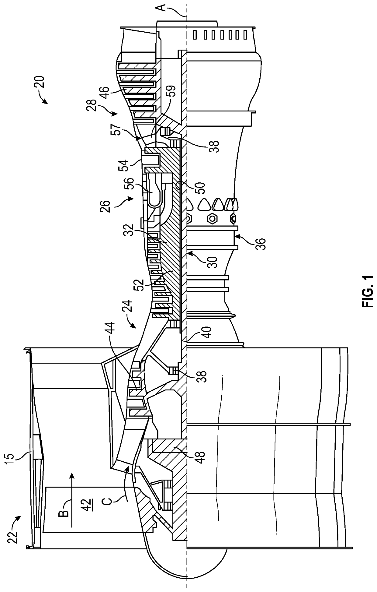
[0035]FIG. 1 schematically illustrates a gas turbine engine 20. As illustratively shown, the gas turbine engine 20 is configured as a two-spool turbofan that has a fan section 22, a compressor section 24, a combustor section 26, and a turbine section 28. The illustrative gas turbine engine 20 is merely for example and discussion purposes, and those of skill in the art will appreciate that alternative configurations of gas turbine engines may employ embodiments of the present disclosure. The fan section 22 includes a fan 42 that is configured to drive air along a bypass flow path B in a bypass duct defined within a nacelle 15. The fan 42 is also configured to drive air along a core flow path C for compression and communication into the combustor section 26 then expansion through the turbine section 28. Although depicted as a two-spool turbofan gas turbine engine in the disclosed non-limiting embodiment, it should be understood that the concepts described herein are not limited to use...


PUM


Abstract

Gas turbine engines are described. The gas turbine engines include a compressor section, a combustor section, a turbine section, and a nozzle, wherein the compressor section, the combustor section, the turbine section, and the nozzle define a core flow path that expels through the nozzle. A waste heat recovery system is operably connected to the gas turbine engine, the waste heat recovery system having a working fluid. An auxiliary cooling system is configured to provide cooling to a working fluid of the waste heat recovery system.

Description

TECHNICAL FIELD[0001]The present disclosure relates generally to systems for recovering waste heat in gas turbine engines, and more specifically to work recovery systems that utilize a supercritical CO2 cycle to recover work from excess heat and generate additional power for the aircraft.BACKGROUND[0002]Gas turbine engines, such as those utilized in commercial and military aircraft, include a compressor section that compresses air, a combustor section in which the compressed air is mixed with a fuel and ignited, and a turbine section across which the resultant combustion products are expanded. The expansion of the combustion products drives the turbine section to rotate. As the turbine section is connected to the compressor section via a shaft, the rotation of the turbine section further drives the compressor section to rotate. In some configurations, a fan is also connected to the shaft and is driven to rotate via rotation of the turbine.[0003]The compression process of the gas tur...

Claims


Application Information

Patent Timeline
IPC IPC(8): F02C7/141
CPCF02C7/141F05D2260/20F02C1/005F02C1/007F02C6/18F02C7/185F05D2220/50F05D2220/62F02C1/10F02C7/224Y02T50/60
Inventor STAUBACH, JOSEPH B.BOUCHER, AMANDA J. L.
Owner RAYTHEON TECH CORP
Why Eureka
Try Eureka