
Using High Rate Telemetry to Improve Drilling Operations

a high-rate telemetry and drilling operation technology, applied in the direction of survey, directional drilling, borehole/well accessories, etc., can solve the problems of limiting the speed, efficiency and safety of well construction operations, slow transmission rate of mud-pulse telemetry and electromagnetic telemetry, and delayed detection and mitigation of abnormal downhole events

Pending Publication Date: 2021-09-30
SCHLUMBERGER TECH CORP
View PDF2 Cites 3 Cited by
  • Summary
  • Abstract
  • Description
  • Claims
  • Application Information

AI Technical Summary

Benefits of technology

The present patent describes methods for drilling oil and gas wells using a wired drill pipe (WDP) string. These methods include using downhole data and a mathematical model to control the drilling operations, such as the rotation of the WDP string and the pumping of drilling fluid. The WDP string can also be moved within the well to perform drilling operations or tripping operations. The technical effects of these methods include improved wellbore stability, reduced stick-slip, and improved wellbore pressure control.

Problems solved by technology

However, relying on rig personnel to manually coordinate the well construction operations, monitor the well construction operations for abnormal conditions and events, and control the well construction equipment in response to such abnormal conditions and events limits speed, efficiency, and safety of the well construction operations.
However, transmission rate for mud-pulse telemetry and electromagnetic telemetry is very slow, often taking between about 30 to 60 seconds for the downhole sensor data to reach the wellsite surface to be analyzed by an equipment controller and / or the rig personnel via the control workstation.
Such slow telemetry transmission rates prevent fast control of downhole equipment from the wellsite surface and result in delayed detection and mitigation of abnormal downhole events.

Method used


Image

  • Using High Rate Telemetry to Improve Drilling Operations
  • Using High Rate Telemetry to Improve Drilling Operations
  • Using High Rate Telemetry to Improve Drilling Operations

Examples


Embodiment Construction

[0028]It is to be understood that the following disclosure provides many different embodiments, or examples, for implementing different features of various embodiments. Specific examples of components and arrangements are described below to simplify the present disclosure. These are, of course, merely examples and are not intended to be limiting. In addition, the present disclosure may repeat reference numerals and / or letters in the various examples. This repetition is for simplicity and clarity, and does not in itself dictate a relationship between the various embodiments and / or configurations discussed.

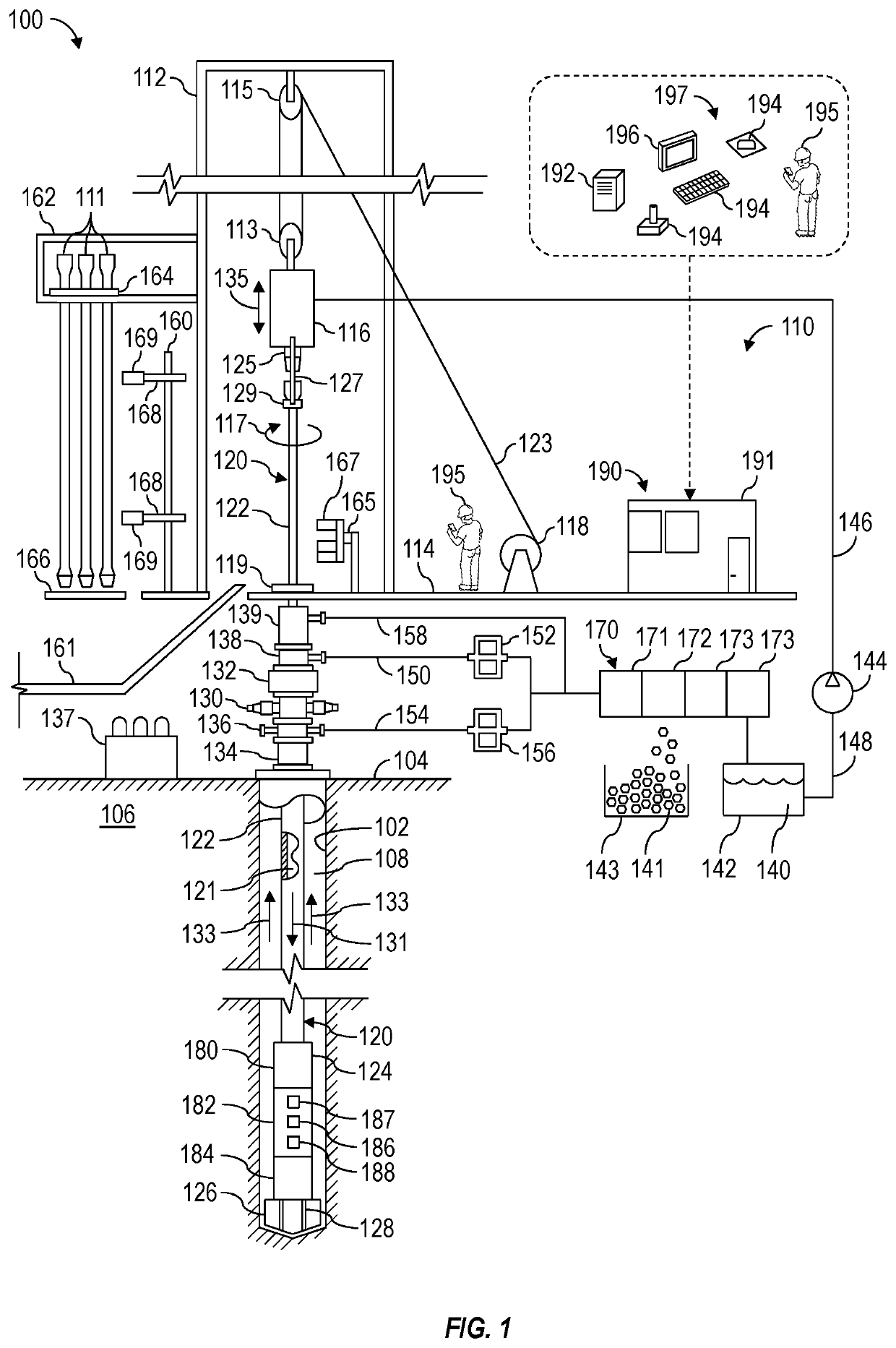
[0029]Systems and methods (e.g., processes, operations) according to one or more aspects of the present disclosure may be utilized or otherwise implemented in association with an automated well construction system (i.e., well construction rig) at an oil and gas wellsite, such as for constructing a wellbore for extracting hydrocarbons (e.g., oil and / or gas) from a subterranean format...


PUM


Abstract

Systems and methods for using high rate telemetry to improve drilling operations. A method may include performing drilling operations with a wired drill pipe (WDP) string in an oil and / or gas well. The drilling operations may include pumping drilling fluid to a mud motor of the WDP string through an internal passage of the WDP string and vertically moving the WDP string via a drawworks while controlling the drawworks to change speed of the WDP string based on downhole data received by wellsite surface equipment via electrical conductors integral to WDP of the WDP string. The received downhole data may include downhole pressure data that is generated downhole by a pressure sensor and is indicative of pressure of the drilling fluid in the internal passage.

Description

BACKGROUND OF THE DISCLOSURE[0001]Wells are generally drilled into the ground or ocean bed to recover natural deposits of oil, gas, and other materials that are trapped in subterranean rock formations. Well construction (e.g., drilling) operations may be performed at a wellsite by a well construction system (e.g., a drilling rig) having various surface and subterranean well construction equipment (e.g., rig equipment) operating in a coordinated manner. For example, a drive mechanism, such as a top drive located at a wellsite surface, can be utilized to rotate and advance a drill string into a subterranean rock formation to drill a wellbore. The drill string may include a plurality of drill pipes coupled together and terminating with a drill bit. Length of the drill string may be increased by adding additional drill pipes while depth of the wellbore increases. Drilling fluid may be pumped from the wellsite surface down through the drill string to the drill bit. The drilling fluid lub...

Claims


Application Information

Patent Timeline
Patent Type & Authority Applications(United States)
IPC IPC(8): E21B44/04E21B47/12E21B7/04E21B3/02E21B4/02E21B47/024E21B21/08E21B19/00
CPCE21B44/04E21B47/12E21B7/04E21B19/008E21B4/02E21B47/024E21B21/08E21B3/022E21B44/00E21B7/067
Inventor WICKS, NATHANIELJOHNSEN, JOERGENPAN, RUI
Owner SCHLUMBERGER TECH CORP
Learn More