
Walkway installation having a handrail connector

a technology for installing walkways and handrails, which is applied in the direction of snow traps, scaffold accessories, rod connections, etc., can solve the problems of undue localised loading of roof structures, inability to and inability to easily and reliably achieve strong and watertight connections

Active Publication Date: 2021-09-23
KEE KLAMP LTD
View PDF9 Cites 7 Cited by
  • Summary
  • Abstract
  • Description
  • Claims
  • Application Information

AI Technical Summary

Benefits of technology

This patent provides a solution for making handrail installations and handrail assemblies that are more resistant to sideways loads. By using a first connector to connect the handrail post to a link, the solution helps to resist any sideways movement of the handrail. This is important because even if a lightweight elongate tread module support is used, the other elongate support is able to handle the load without causing any torsional load on it. This results in a better resistance to sideways deflection for the handrail and post.

Problems solved by technology

Securing a handrail post directly to a roof structure can provide a firm location for the handrail but achieving a strong and watertight connection often cannot be readily and reliably accomplished.
In particular, attaching directly to the roof structure creates a risk of undue localised loading of the roof structure and associated risk that the integrity of a watertight connection might be compromised.
Because of the general desirability, particularly for rooftop installations, for the walkway to be of a low weight that does not disadvantageously apply additional loading to the roof structure there is the potential problem that the walkway may have insufficient strength to provide adequate support for handrail posts.
Thus a walkway assembly of that type of construction is not necessarily suitable for firmly supporting a handrail.

Method used


Image

  • Walkway installation having a handrail connector
  • Walkway installation having a handrail connector
  • Walkway installation having a handrail connector

Examples


Embodiment Construction

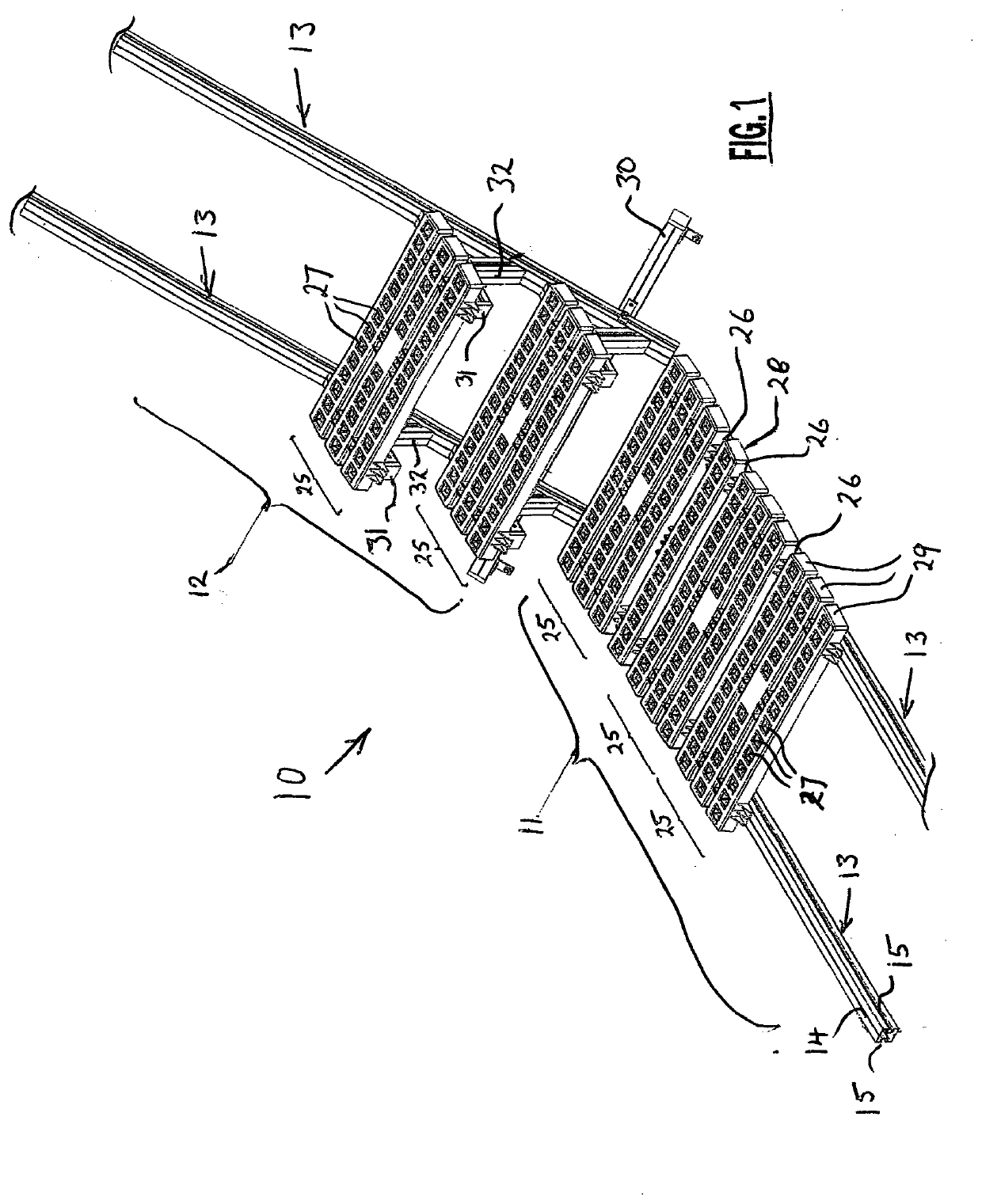
[0039]A walkway assembly 10 for securing to a roof structure of the type comprising a flat section and an inclined section comprises a horizontal walkway assembly section 11 and a stairway assembly section 12.

[0040]The walkway and stairway assemblies 11,12 each comprise a pair of mutually parallel elongate primary support members each in the form of a beam 13, the two support beams lying side by side in spaced apart relationship.

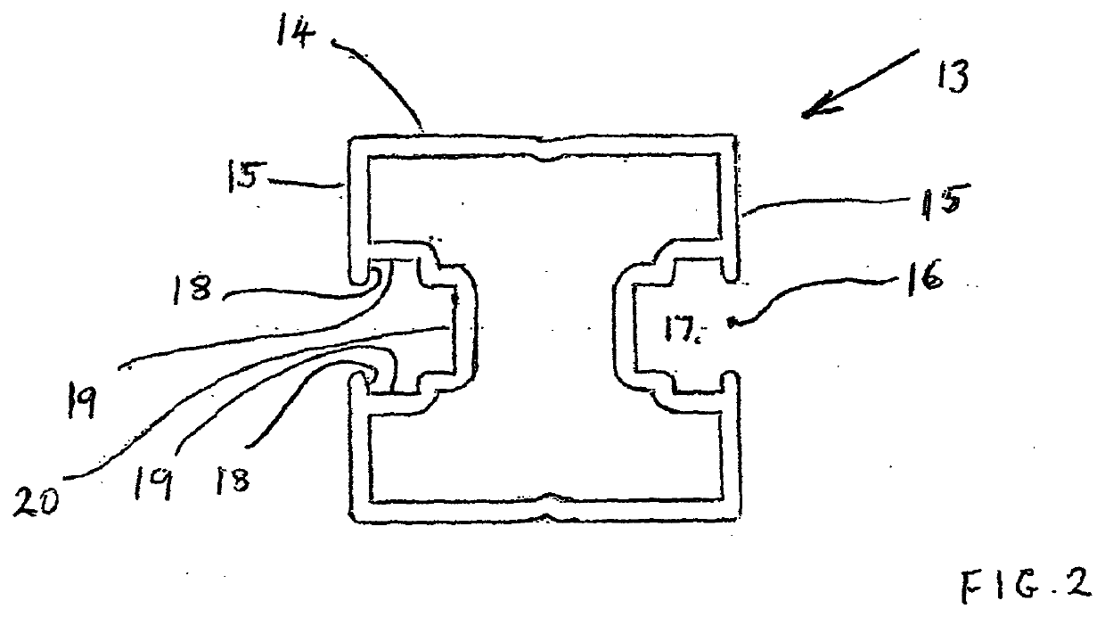
[0041]Each beam 13 (see FIG. 2) is an aluminium extrusion comprising an upper support surface 14 and a pair of side face walls 15 each of which is grooved such that in each side wall there is an opening 16 to a substantially C shaped retention channel 17 as viewed in transverse cross-section.

[0042]The channels 17 in each side face are of the same cross-sectional shape and comprise a pair of abutment surfaces 18 disposed respectively above and below the opening 16. The cross-section of each channel departs from an exact C shape in that the channel has upper a...


PUM


Abstract

A walkway installation includes a walkway assembly which includes at least one tread module supported by a pair of spaced apart elongate supports which extend in the direction of the length of the walkway installation, the walkway installation additionally including a handrail assembly including a handrail which extends in the direction of the length of the walkway assembly and a plurality of spaced apart posts which each secure the handrail relative to the walkway assembly, the handrail assembly additionally including a first connector which secures a post to one side of the walkway assembly and the first connector having secured thereto a substantially inflexible transverse link which extends across the walkway assembly in a direction perpendicular to the length of the walkway installation, the transverse link extending to a second connector secured to the other side of the walkway.

Description

CROSS-REFERENCE TO RELATED APPLICATIONS[0001]This application is the U.S. national phase of International Application No. PCT / GB2019 / 000095 filed Jul. 9, 2019 which designated the U.S. and claims priority to GB 1811514.7 filed Jul. 13, 2018, the entire contents of each of which are hereby incorporated by reference.BACKGROUND OF THE INVENTIONField of the Invention[0002]This invention relates to a handrail assembly, a walkway installation comprising a handrail assembly, and a connector for use in securing a handrail to a walkway.Description of the Related Art[0003]For pedestrian walkways provided at exposed locations, typically at elevated locations or in proximity to hazardous material, it is desirable to provide a handrail assembly that acts as a barrier to restrain personnel from falling from the walkway.[0004]If the walkway is provided at a location which is away from a wall or other such structure to which a handrail may be directly secured it is necessary to secure the handrail ...

Claims


Application Information

Patent Timeline
IPC IPC(8): E04F11/18E04D13/12
CPCE04F11/1812E04F2011/1889E04D13/12E04F11/1817F16B7/187F16B7/0493F16B9/054F16B9/058E04G5/14E04G1/15E04G5/10E04G27/00E04F11/025E04F11/06F16B7/00
Inventor OWEN, STUART
Owner KEE KLAMP LTD
Learn More