
Device and method for joining a lens to a housing of a lighting device of a motor vehicle

a technology for motor vehicles and housings, applied in the direction of manufacturing tools, transportation and packaging, lighting and heating apparatus, etc., can solve the problems of high cost, manufacturing process, and only account for dimensional deviations in functional dimensions

Active Publication Date: 2021-09-16
HELLA KG HUECK & CO
View PDF0 Cites 0 Cited by
  • Summary
  • Abstract
  • Description
  • Claims
  • Application Information

AI Technical Summary

Benefits of technology

The present invention provides a device and method for aligning a holding device relative to a receptacle device without damaging the preheater elements. This is achieved through the use of a pre-centering device that compensates for any tolerances between the two elements. The holding device is attached to the pre-centering device during the alignment procedure, allowing for precise alignment relative to the receptacle device. The holding device can be easily attached and released from the pre-centering device, and the receptacle device and its internal components can remain in a fixed position during the joining process, reducing the likelihood of collisions and improving the reliability of the device. The holding device can be attached to a tool upper part in a fixed position during the joining process.

Problems solved by technology

However, this alignment procedure only accounts for dimensional deviations in functional dimensions, which is to say a lens that is too small on a housing that is too large, for example.
This manufacturing process therefore has a major weakness, since it only allows for a stable manufacturing process or components with zero deviation in single-component manufacturing / prefabrication.
This results in defect investigation, interventions in the ongoing manufacturing process, and other measures that cause high costs, especially in production.
Often, the geometric reserves of the components with regard to relative displacement are limited, since the geometric minimum distances between the housing and the required radiant preheaters are smaller than the geometric reserves in the configuration of the weld seam.
The displacement of the housing receptacle relative to the lens provided by default for tolerance compensation is thus limited.
However, as a result of the change in the position of the receptacle device, and thus also of the housing accommodated in the receptacle device, a realignment of the housing receptacle relative to the receptacle on the top side for accommodating the lens can result in a collision between the internal components already placed in the housing and the joining device, as for example infrared heaters moving inward to heat the edge regions of the lens and housing to be joined; consequently the housing receptacle should be moved out of the zero position to the position of the head section beforehand if the position of the preheater was not changed.

Method used


Image

  • Device and method for joining a lens to a housing of a lighting device of a motor vehicle

Examples


Embodiment Construction

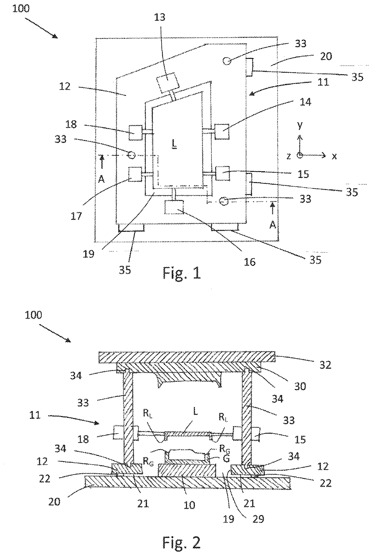
[0022]Shown schematically in FIGS. 1 and 2 is a device 100 for installing a lens L on a housing G of a lighting device of a motor vehicle. The lens L is attached to the housing G by means of a joining process, in particular a welding process, in that the edge region RL of the lens L is integrally connected to the edge region RG of the housing G. Prior to the joining, the lens L and housing G must be aligned with one another in order to compensate for tolerance deviations.

[0023]The device 100 has a receptacle device 10, as can be seen in FIG. 2, to accommodate the housing G. In the receptacle device 10, the housing G can be aligned on a reference point system by placing the housing G on this reference point system. The reference point system can have multiple reference points spaced apart from one another, which are spread out or positioned in an x-y plane. A defined positioning of the housing G in the receptacle device 10, and thus in the device 100, can be accomplished by means of ...


PUM

PropertyMeasurementUnit
displacementaaaaaaaaaa
welding forcesaaaaaaaaaa
distancesaaaaaaaaaa

Abstract

A method for joining a lens to a housing of a lighting device of a motor vehicle, in which the housing is accommodated and secured in a receptacle device. The method includes accommodating the lens in a pre-centering device, aligning the lens towards the housing during an alignment procedure and accommodating the lens by a holding device after the alignment procedure. The method further includes holding the lens by the holding device during a subsequent joining process, releasably attaching the holding device to the pre-centering device, aligning, via fastening elements, during the alignment procedure and moving the accommodated lens and the holding device attached to the pre-centering device relative to the receptacle device such that the lens and the holding device are aligned on the housing accommodated in the receptacle device.

Description

[0001]This nonprovisional application is a Divisional Application of U.S. application Ser. No. 16 / 288,724, which was filed on Feb. 28, 2019, and is a continuation of International Application No. PCT / EP2017 / 071306, which was filed on Aug. 24, 2017, and which claims priority to German Patent Application No. 10 2016 116 131.4, which was filed in Germany on Aug. 30, 2016, and which are both herein incorporated by reference.BACKGROUND OF THE INVENTIONField of the Invention[0002]The present invention relates to a device for joining a lens to a housing of a lighting device of a motor vehicle. The invention additionally relates to a method for installing a lens on a housing of a lighting device of a motor vehicle.Description of the Background Art[0003]During installation of a lighting device, such as a taillight for example, in the body of a motor vehicle, it is a critical requirement that the gap profile or joint profile between the installed lighting device and the body maintains the clo...

Claims


Application Information

Patent Timeline
Patent Type & Authority Applications(United States)
IPC IPC(8): B62D65/16F21S43/27B29C65/78B29C65/00B23P19/04B23P19/10
CPCB62D65/16F21S43/27B29C65/7802B29L2031/30B29C66/54B23P19/04B23P19/10B29C65/7841B29L2031/747B29C65/02B29C65/06B29C65/1432B29C65/1412B29C66/8322B29C65/7847
Inventor SCHUETTE, ANDREAS
Owner HELLA KG HUECK & CO
Learn More