
Coil component

Pending Publication Date: 2021-09-09
TDK CORPARATION
View PDF0 Cites 0 Cited by
  • Summary
  • Abstract
  • Description
  • Claims
  • Application Information

AI Technical Summary

Benefits of technology

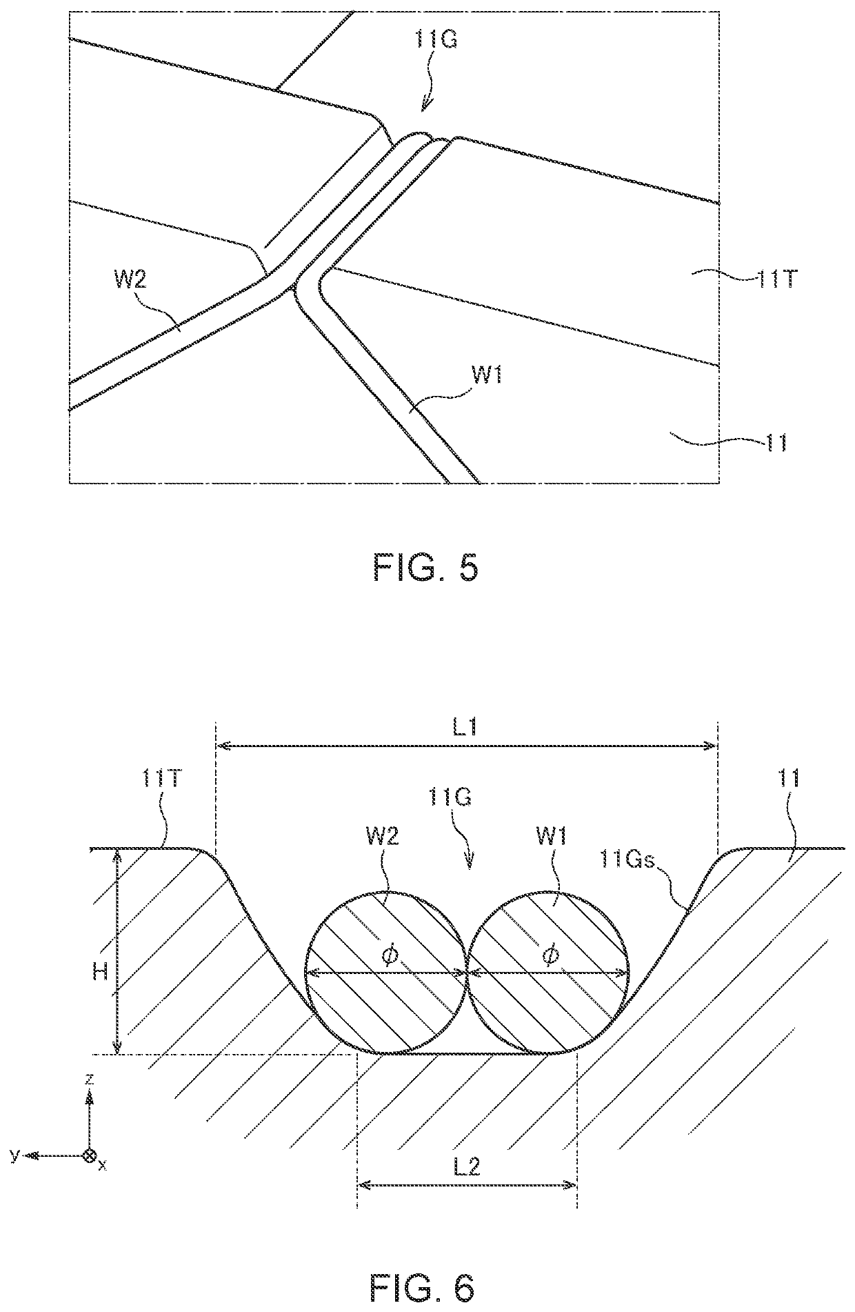
The present invention provides a coil component with improved working efficiency and reduced variation in characteristics, such as an S parameter. This is achieved by winding multiple wires around a drum-shaped core and accommodating them in grooves on the core. The grooves have a tapered shape to enhance positioning of the wires and prevent variation in characteristics due to shifting of the wires. The space factor of the wires in each groove should be 60% or higher to maintain high magnetic characteristics. The coil component may also have a plate-like core with grooves formed on its surfaces to prevent interference between the wires and the core. Overall, the invention allows for efficient and reliable manufacturing of coil components.

Problems solved by technology

In the coil component described in JP 2018-148081A, the vicinities of the end portions of the two wires are significantly separated, so that, when this coil component is used as a common mode choke coil, a large variation disadvantageously occurs in characteristics such as an S parameter.
To solve such a disadvantage, there can be conceived a method of forming a groove in the flange part and accommodating a wire in the formed groove; however, depending on the shape or size of the groove, it may be difficult to accommodate the wires in the groove during the manufacture of the coil component and to sufficiently reduce variation in characteristics such as an S parameter.

Method used


Image

  • Coil component
  • Coil component
  • Coil component

Examples


first embodiment

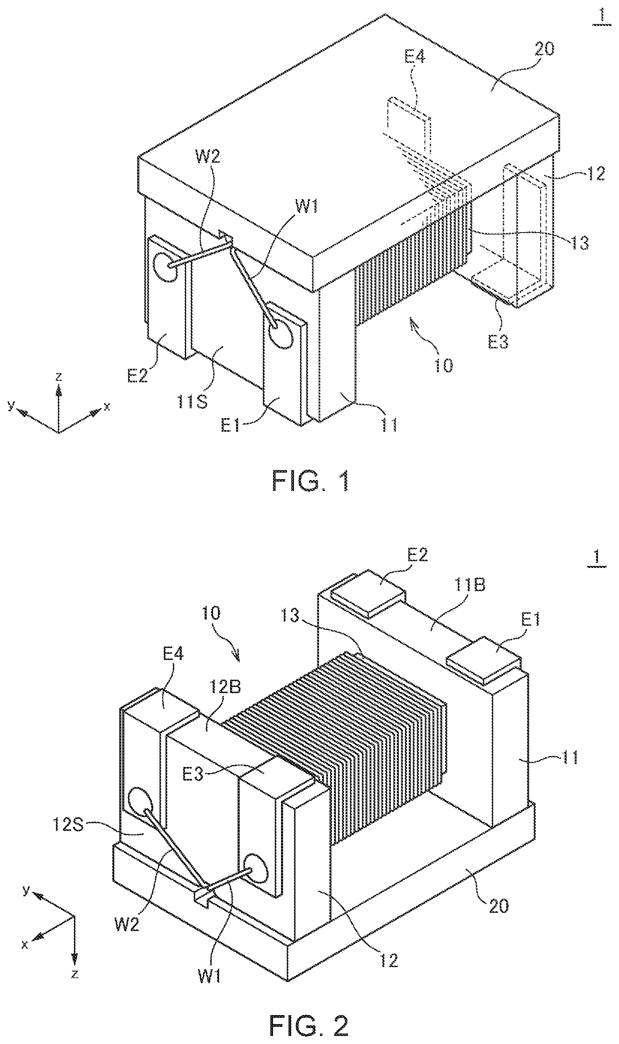
[0025]FIGS. 1 and 2 are schematic perspective views illustrating the outer appearance of a coil component 1 according to a first embodiment of the present invention.

[0026]The coil component 1 according to the present embodiment is a common mode choke coil and includes, as illustrated in FIGS. 1 and 2, a drum-shaped core 10, a plate-like core 20, terminal electrodes E1 to E4, and wires W1 and W2. As a material for the drum-shaped core 10 and plate-like core 20, a magnetic material having a high permeability such as ferrite is used. The same magnetic material or different magnetic materials may be used for the drum-shaped core 10 and the plate-like core 20, and the magnetic material preferably has a permeability μ of 10 to 4000 H / m.

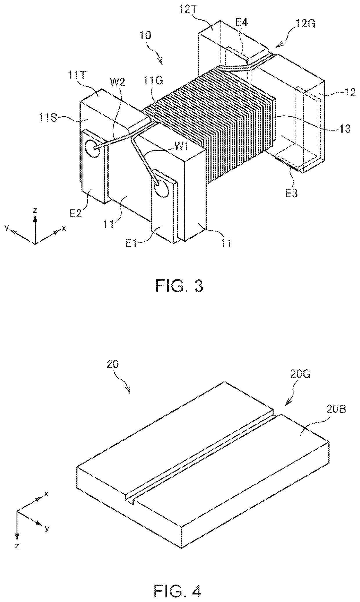
[0027]FIG. 3 is a schematic perspective view illustrating a state where the plate-like core 20 is removed from the coil component 1.

[0028]As illustrated in FIGS. 1 to 3, the drum-shaped core 10 includes a winding core part 13 with its axis directed in the x...

second embodiment

[0041]FIG. 9 is a schematic perspective view illustrating the outer appearance of a coil component 2 according to a second embodiment of the present invention. FIG. 10 is a schematic perspective view illustrating a state where the plate-like core 20 is removed from the coil component 2. FIG. 11 is a schematic perspective view illustrating the outer appearance of the plate-like core 20 used in the second embodiment.

[0042]As illustrated in FIGS. 9 and 10, in the coil component 2 according to the second embodiment, two grooves 11G1 and 11G2 are formed in the flange part 11, and two grooves 12G1 and 12G2 are formed in the flange part 12. A groove 20G1 is formed in the surface 20B of the plate-like core 20 so as to overlap the grooves 11G1 and 12G1, and a groove 20G2 is formed in the surface 20B so as to overlap the grooves 11G2 and 12G2.

[0043]The leading portion of the wire W1 is accommodated in the grooves 11G1 and 12G1, and the leading portion of the wire W2 is accommodated in the gro...

third embodiment

[0046]FIG. 12 is a schematic perspective view illustrating the outer appearance of a coil component 3 according to a third embodiment of the present invention. FIG. 13 is a schematic perspective view illustrating a state where the plate-like core 20 is removed from the coil component 3.

[0047]As illustrated in FIGS. 12 and 13, in the coil component 3 according to the third embodiment, the groove 11G is formed in the xz surface of the flange part 11, and the groove 12G is formed in the xz surface of the flange part 12. Thus, the grooves 11G and 12G are not closed by the plate-like core 20, and the inner walls thereof are exposed in the y-direction. In the present embodiment, the groove 20G need not be formed in the plate-like core 20. Other basic configurations are the same as those of the coil component 1 according to the first embodiment, so the same reference numerals are given to the same elements, and overlapping description will be omitted.

[0048]In the present embodiment as well...


PUM


Abstract

Disclosed herein is a coil component that includes: a drum-shaped core including a first flange part, a second flange part, and a winding core part positioned between the first and second flange parts; a plurality of first terminal electrodes provided on the first flange part; a plurality of second terminal electrodes provided on the second flange part; and a plurality of wires wound around the winding core part, each of the plurality of wires having a first end connected to an associated one of the first terminal electrodes, and having a second end connected to an associated one of the second terminal electrodes. Each of the first and second flange parts has a tapered groove whose side surfaces are inclined. The plurality of wires are accommodated in the tapered grooves.

Description

BACKGROUND OF THE INVENTIONField of the Invention[0001]The present invention relates to a coil component and, more particularly, to a coil component using a drum-shaped core.Description of Related Art[0002]As a coil component using a drum-shaped core, a coil component described in JP 2018-148081A is known. The coil component described in JP 2018-148081A has two wires wound around a winding core part of a drum-shaped core thereof, and one end of each of the two wires is connected to a terminal electrode provided on one flange part, and the other end thereof is connected to a terminal electrode provided on the other flange part.[0003]In the coil component described in JP 2018-148081A, the vicinities of the end portions of the two wires are significantly separated, so that, when this coil component is used as a common mode choke coil, a large variation disadvantageously occurs in characteristics such as an S parameter. To solve such a disadvantage, there can be conceived a method of fo...

Claims


Application Information

Patent Timeline
IPC IPC(8): H01F27/28H01F27/26H01F27/29H01F41/02H01F41/064
CPCH01F27/2823H01F27/26H01F41/064H01F41/0206H01F27/29H01F27/2828H01F3/10H01F17/045H01F2017/0093
Inventor ASAI, YUGOTOKIWA, AOIURABE, DAISUKE
Owner TDK CORPARATION
Learn More