
Downhole Conveyance Line Cutter

a technology of conveyance line cutter and downhole, which is applied in the direction of drilling casings, drilling pipes, borehole/well accessories, etc., can solve the problems of complicated testing, completion, intervention, and other downhole operations, and it is more likely that tool strings or other downhole equipment may become stuck or jammed within the wellbor

Active Publication Date: 2021-09-02
IMPACT SELECTOR INT LLC
View PDF0 Cites 2 Cited by
  • Summary
  • Abstract
  • Description
  • Claims
  • Application Information

AI Technical Summary

Benefits of technology

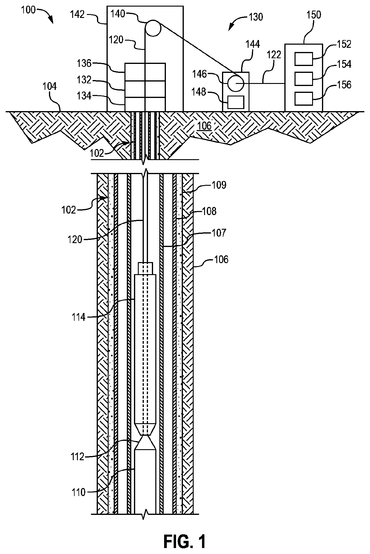
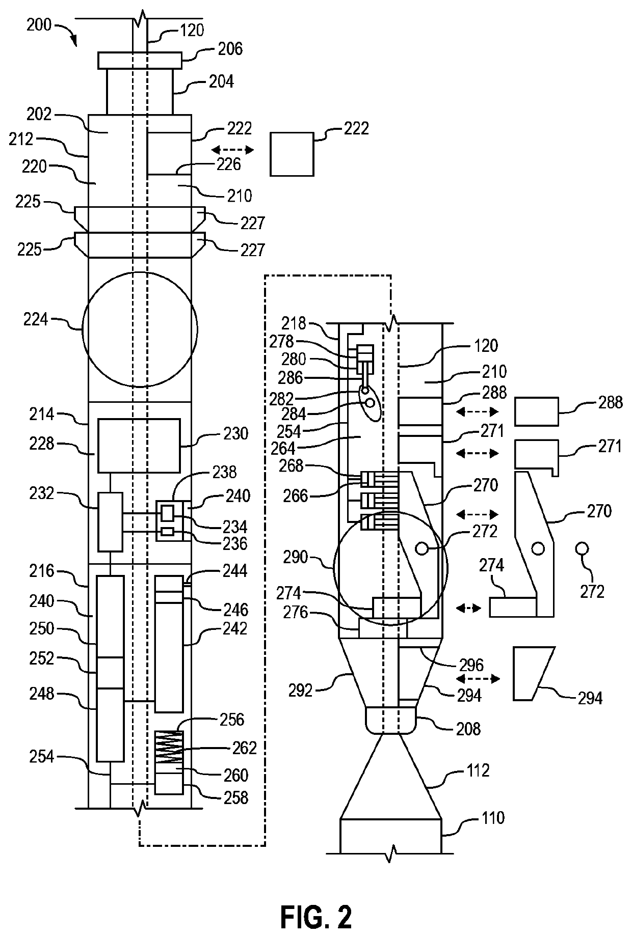
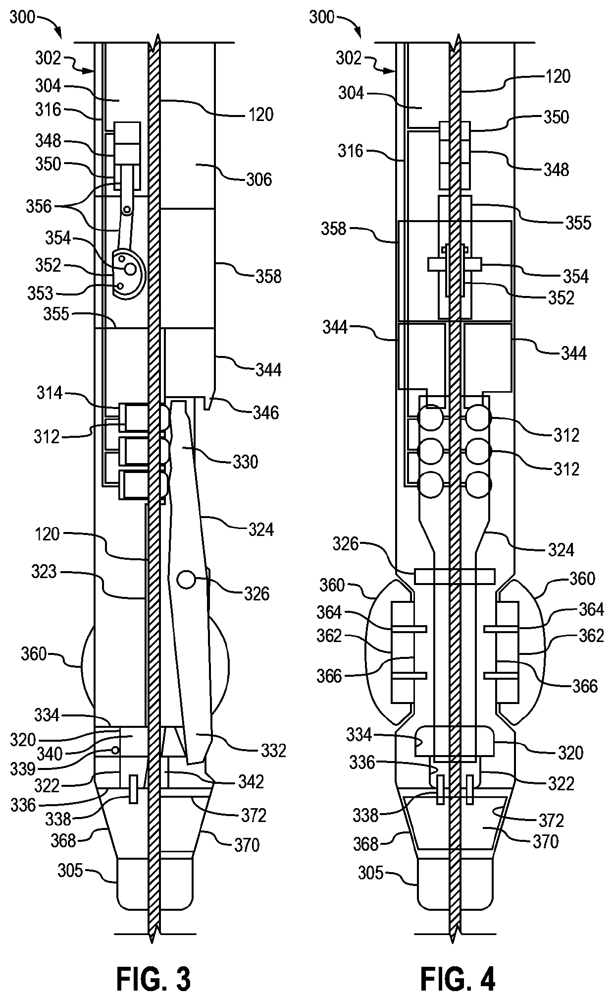
The present patent describes a downhole tool that can be used in a wellbore to cut a conveyance line that carries a tool string. The tool has a body, a fluid chamber, a piston, a knife, an arm, and a fluid source. The tool can be conveyed downhole along the conveyance line and then cut the conveyance line with the knife. Additionally, the patent also describes a variation of the tool where the nose section is larger in diameter than the body and can make contact with the tool string. The tool can also be connected to the conveyance line with a clamping mechanism. The technical effect of this invention is to provide a reliable and efficient tool for cutting conveyance lines in wellbore operations.

Problems solved by technology

Such testing, completion, intervention, and other downhole operations have become complicated, as wellbores are drilled deeper and through more difficult materials.
However, in working with deeper and more complex wellbores, it has become more likely that a tool string or other downhole equipment may become stuck or jammed within a wellbore.

Method used


Image

  • Downhole Conveyance Line Cutter
  • Downhole Conveyance Line Cutter
  • Downhole Conveyance Line Cutter

Examples


Embodiment Construction

[0025]It is to be understood that the following disclosure provides many different embodiments, or examples, for implementing different features of various embodiments. Specific examples of components and arrangements are described below to simplify the present disclosure. These are, of course, merely examples and are not intended to be limiting. In addition, the present disclosure may repeat reference numerals and / or letters in the various examples. This repetition is for simplicity and clarity, and does not in itself dictate a relationship between the various embodiments and / or configurations discussed. Moreover, the formation of a first feature over or on a second feature in the description that follows, may include embodiments in which the first and second features are formed in direct contact, and may also include embodiments in which additional features may be formed interposing the first and second features, such that the first and second features may not be in direct contact...


PUM


Abstract

A downhole conveyance line cutter operable to be conveyed downhole within a wellbore along a conveyance line that conveys a tool string within the wellbore and then cut the conveyance line. The downhole conveyance line cutter may have a body, a fluid chamber within the body, a piston slidably disposed within the fluid chamber, a knife that is movable with respect to the body, an arm operatively connecting the piston and the knife, and a fluid source operable to pump a fluid into the fluid chamber to cause the piston to move the arm which moves the knife to cut the conveyance line.

Description

CROSS-REFERENCE TO RELATED APPLICATIONS[0001]This application claims priority to and the benefit of U.S. Provisional Application No. 62 / 983,245, titled “DOWNHOLE CONVEYANCE LINE CUTTER,” filed Feb. 28, 2020, the entire disclosure of which is hereby incorporated herein by reference.BACKGROUND OF THE DISCLOSURE[0002]Wells are generally drilled into land surface or ocean bed to recover natural deposits of oil, gas, and other natural resources that are trapped in subterranean geological formations in the Earth's crust. Testing and evaluation of completed and partially finished wells has become commonplace, such as to increase well production and return on investment. Downhole measurements (e.g., formation pressure, formation permeability, etc.) and recovery of formation fluid samples may be useful for predicting economic value, production capacity, and production lifetime of geological formations. Completion and stimulation operations of wells, such as perforating and fracturing operati...

Claims


Application Information

Patent Timeline
Patent Type & Authority Applications(United States)
IPC IPC(8): E21B29/04E21B17/02
CPCE21B29/04E21B17/023
Inventor MASSEY, JAMES PATRICK
Owner IMPACT SELECTOR INT LLC
Learn More