
Electric motor controlling system and vibration suppression method for using the same

a technology of electric motors and control systems, applied in the direction of electric motor control, general control strategies, transportation and packaging, etc., can solve the problems of dangerous driving, dangerous driving, and dangerous driving, so as to reduce the risk of accident, and improve the riding comfortability of electric vehicles.

Active Publication Date: 2021-08-26
DELTA ELECTRONICS INC
View PDF0 Cites 2 Cited by
  • Summary
  • Abstract
  • Description
  • Claims
  • Application Information

AI Technical Summary

Benefits of technology

This patent is for a system and method for controlling the vibration of an electric motor in an electric vehicle. By using a compensator, the system can suppress abnormal twisting and vibration caused by the vehicle's transmission mechanisms, improving the rider's comfort. The system also allows for fine adjustments to the parameters used to suppress vibration, making it easy to adapt to different vehicle types. Overall, this technology improves the user-friendliness and convenience of electric vehicles.

Problems solved by technology

These environments cannot stand waste gas which may damage people's health.
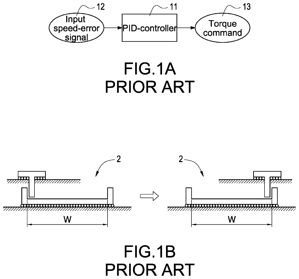
However, the aforementioned speed control code cannot overcome vibration issues caused by mechanical characteristics of the transmission mechanism (such as gearbox, steering differential, etc.) of the electric vehicle while the electric vehicle is running, and driver's maneuverability and riding comfortability will be extremely affected.
As a result, the electric vehicle may face problems such as poor response, abnormal twisting, vibration, etc., when the gears 2 inside the electric vehicle are located in the aforementioned dead zone.
For example, it may cause vibration and reduce driver's riding comfortability when the traction motors of the electric vehicle work within specific operation zones.
Therefore, unwilling work status may occur to the electric vehicle.

Method used


Image

  • Electric motor controlling system and vibration suppression method for using the same
  • Electric motor controlling system and vibration suppression method for using the same
  • Electric motor controlling system and vibration suppression method for using the same

Examples


first embodiment

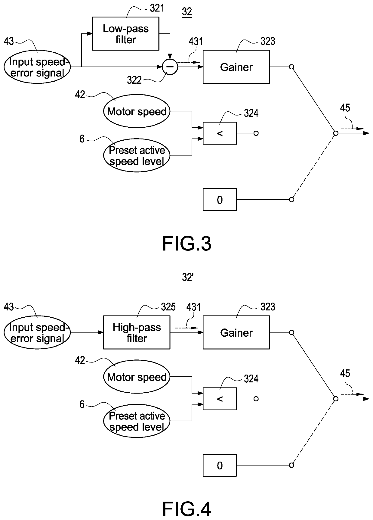
[0047]FIG. 3 is a block diagram of a vibration suppression compensator according to the present invention. Please refer to FIG. 2 and FIG. 3 together for illustrating the following each embodiment. In the embodiment shown in FIG. 3, the vibration suppression compensator 32 can be implemented by hardware, software, or their combination, and divided into multiple parts including a low-pass filter 321, a processor 322, a gainer 323, and a comparator 324, according to respective functions.

[0048]The low-pass filter 321 receives the input speed-error signal 43, and the low-pass filter 321 performs a filtering process to the input speed-error signal 43 for retrieving low frequency signal from the input speed-error signal 43. The processor 322 receives the input speed-error signal 43 and the low frequency signal of the input speed-error signal 43 from the low-pass filter 321, and the processor 322 then outputs a high frequency signal 431 of the input speed-error signal 43 by subtracting the...

second embodiment

[0055]FIG. 4 is a block diagram of a vibration suppression compensator according to the present invention. FIG. 4 discloses another vibration suppression compensator 32′. The vibration suppression compensator 32′ can be implemented by hardware, software, or their combination, and divided into multiple parts including a high-pass filter 325, a gainer 323, and a comparator 324, according to respective functions.

[0056]In this embodiment, the vibration suppression compensator 32′ receives the input speed-error signal 43 through the high-pass filter 325, and performs the filtering process to the input speed-error signal 43 by the high-pass filter 325 for retrieving high frequency signal 431 directly from the input speed-error signal 43. In comparison to the embodiment disclosed in FIG. 3, it is unnecessary for the vibration suppression compensator 32′ in this embodiment of FIG. 4 to additionally arrange with the processor 322 (shown in FIG. 3), and the calculation of subtracting the inpu...


PUM


Abstract

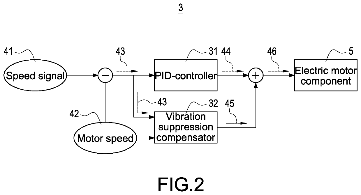
An electric motor controlling system used for vibration suppression of an electric vehicle is disclosed. The controlling system includes a PID-controller and a vibration suppression compensator. The PID-controller generates a basic torque command through performing a calculation based on input speed-error signal of the electric vehicle, the vibration suppression compensator generates a compensated torque command through performing a compensation gain procedure on the input speed-error signal. The vibration suppression compensator further receives a motor speed of the electric vehicle, sets its output as the compensated torque command when the motor speed is smaller than a preset active speed level, otherwise sets the output as 0. The controlling system generates an output torque command via adding up the basic torque command and the output of the vibration suppression compensator, and operates electric motor components of the electric vehicle according to the output torque command.

Description

BACKGROUND OF THE INVENTION1. Field of the Invention[0001]The invention relates to a controlling system, and in particularly to an electric motor controlling system, and a vibration suppression method applied to the electric motor controlling system.2. Description of Related Art[0002]Recently, an industrial vehicle, such as a forklift, automatic guided vehicle (AGV), etc., as one of the electric apparatuses has largest-scaled electrification and is well accepted by the market. The application environments of the industrial vehicles are mostly indoor spaces such as factories, warehouses, etc. These environments cannot stand waste gas which may damage people's health. Therefore, compared to the vehicles for people's livelihood, electrified industrial vehicles are more acceptable to the market.[0003]Though current industrial vehicles still have basic requirements for maneuverability and riding comfortability; however, compare to the vehicles for people's livelihood, the transmission me...

Claims


Application Information

Patent Timeline
Patent Type & Authority Applications(United States)
IPC IPC(8): H02P23/04H02P23/00
CPCH02P23/04B60L15/20H02P23/0004H02P29/00H02P23/14B60L2240/421B60L2240/423Y02T10/72B60L2270/145B60L2240/12Y02T10/64B60L2200/42B60L2260/40
Inventor TSAO, CHUN-CHIAHUANG, CHIEN-PING
Owner DELTA ELECTRONICS INC
Learn More