Stack for an energy storage device

Pending Publication Date: 2021-08-26
DYSON TECH LTD
View PDF0 Cites 0 Cited by
  • Summary
  • Abstract
  • Description
  • Claims
  • Application Information

AI Technical Summary

Benefits of technology

The patent describes a technique for analyzing laser ablation products using mass-spec to quickly determine their characteristics. These characteristics can be used to guide the production and processing of an energy storage device. By correlating the position of the laser ablation with the speed of movement of the stack, the technique allows for efficient and cost-effective determination of the characteristic's location without needing to directly measure the stack's travel. The technical effect of this patent is to provide a fast and efficient way to analyze and produce energy storage devices.

Problems solved by technology

However, known formation and processing of stacks for energy storage devices such as solid-state thin film cells can be inefficient and / or of limited reliability, making effective commercialisation difficult.

Method used


Image

  • Stack for an energy storage device
  • Stack for an energy storage device
  • Stack for an energy storage device

Examples


Embodiment Construction

[0035]Details of methods, structures and devices according to some embodiments will become apparent from the following description, with reference to the Figures. In this description, for the purpose of explanation, numerous specific details of certain examples are set forth. Reference in the specification to “an example,”“an embodiment,” or similar language means that a particular feature, structure, or characteristic described in connection with the example / embodiment is included in at least that one example / embodiment, but not necessarily in other examples / embodiments. It should further be noted that certain examples / embodiments are described schematically with certain features omitted and / or necessarily simplified for ease of explanation and understanding of the concepts underlying the examples / embodiments.

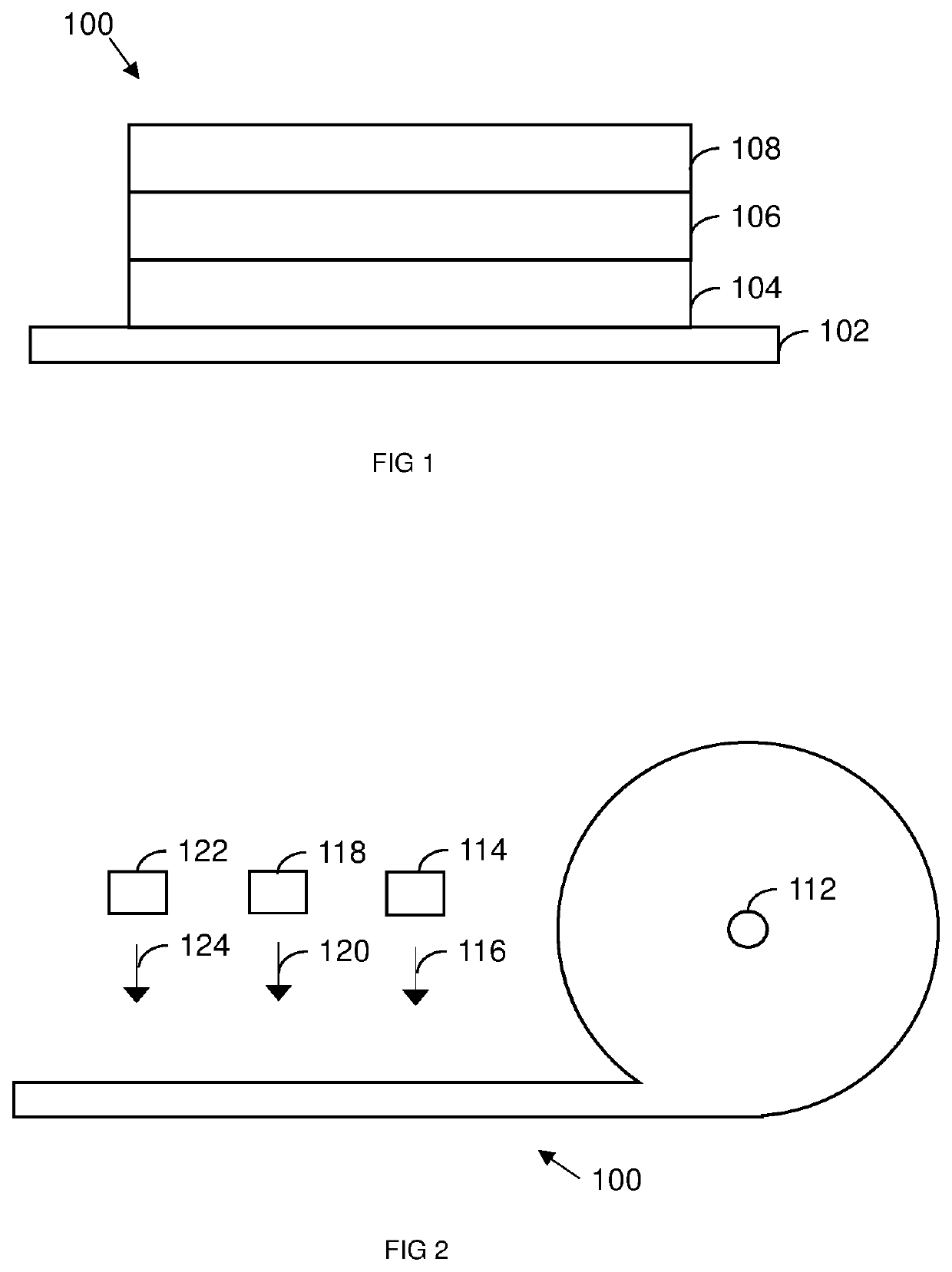
[0036]FIG. 1 shows a stack 100 of layers for an energy storage device. The stack 100 of FIG. 1 may be used as part of a thin film energy storage device having a solid electrol...


PUM

PropertyMeasurementUnit
Speedaaaaaaaaaa
Depthaaaaaaaaaa

Abstract

A method comprises obtaining a stack for an energy storage device, the stack comprising one or more layers; laser ablating the stack so as to form a cut through one or more of the layers, thereby producing one or more laser ablation products; and analysing, using a mass spectrometry-based analysis technique, the laser ablation products thereby to determine one or more characteristics of the stack. Also disclosed is an apparatus.

Description

REFERENCE TO RELATED APPLICATIONS[0001]This application is a national stage application under 35 U.S.C. 371 of International Application No. PCT / GB2019 / 052040, filed Jul. 19, 2019, which claims the priority of United Kingdom Application No. 1811879.4, filed Jul. 20, 2018, the entire contents of each of which are incorporated herein by reference.FIELD OF THE DISCLOSURE[0002]The present disclosure relates to a stack for an energy storage device, and, more specifically, although not exclusively, to methods and apparatus for processing a stack for an energy storage device.BACKGROUND OF THE DISCLOSURE[0003]A known method of producing energy storage devices such as solid-state thin film cells comprising layers of electrodes, electrolyte and current collectors is to first form a stack comprising a first current collecting layer formed on a substrate, an electrode layer, an electrolyte layer, a second electrode layer and a second current collecting layer. The stack is then cut into separate...

Claims


Application Information

Patent Timeline
IPC IPC(8): H01M10/0585H01J49/04H01J49/16H01J49/10H01J49/00
CPCH01M10/0585H01J49/04H01J49/0004H01J49/105H01J49/164H01J49/0463Y02E60/10Y02P70/50H01G9/15H01G11/84H01M6/40H01M10/04B23K26/364B23K31/12G01N27/623H01M2300/0065H01M2300/0068
Inventor RENDALL, MICHAEL EDWARD
Owner DYSON TECH LTD
Why Eureka
Try Eureka