
Height Adjustable Rest

Pending Publication Date: 2021-08-12
VALTRA
View PDF0 Cites 0 Cited by
  • Summary
  • Abstract
  • Description
  • Claims
  • Application Information

AI Technical Summary

Benefits of technology

The patent describes a device that is used to support heavy objects. It has a flange on top of a cylindrical post to provide a stable surface for proping up objects. The device also has a snap ring fitted around the tube body to prevent the post from dropping off. Additionally, there are knob and base holes along with rods to provide increased torque power for adjusting the height of the object being supported. The device also has matching screw thread portions to protect the threads from damage.

Problems solved by technology

Available products on the market are either difficult to operate because of insufficient torque when dealing with large / heavy work pieces or that the turning threads on the products get damaged easily due to the exposed design.

Method used


Image

  • Height Adjustable Rest
  • Height Adjustable Rest
  • Height Adjustable Rest

Examples


Embodiment Construction

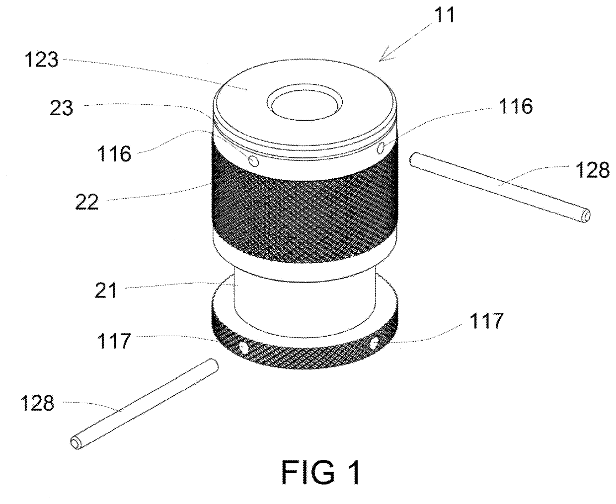
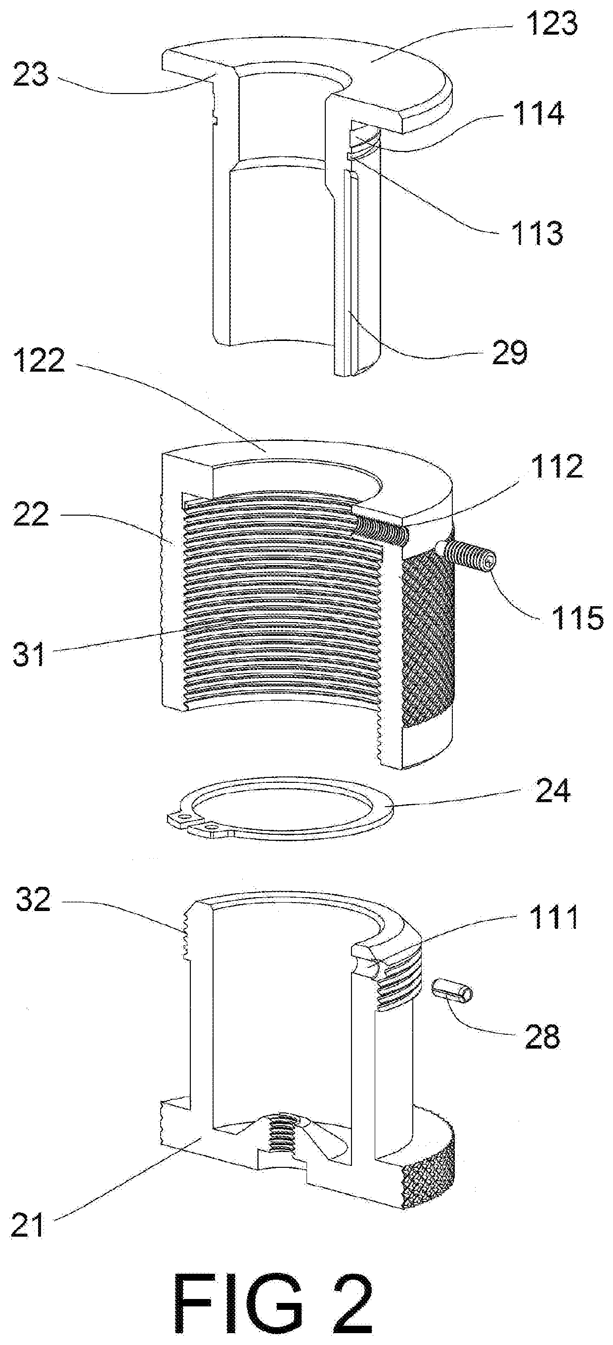
[0022]The height adjustable rest 11 of present invention is comprised of four main parts: a base 21, a cylindrical knob 22, a cylindrical post 23 and a snap ring 24. The four main parts can be seen in FIG. 2.

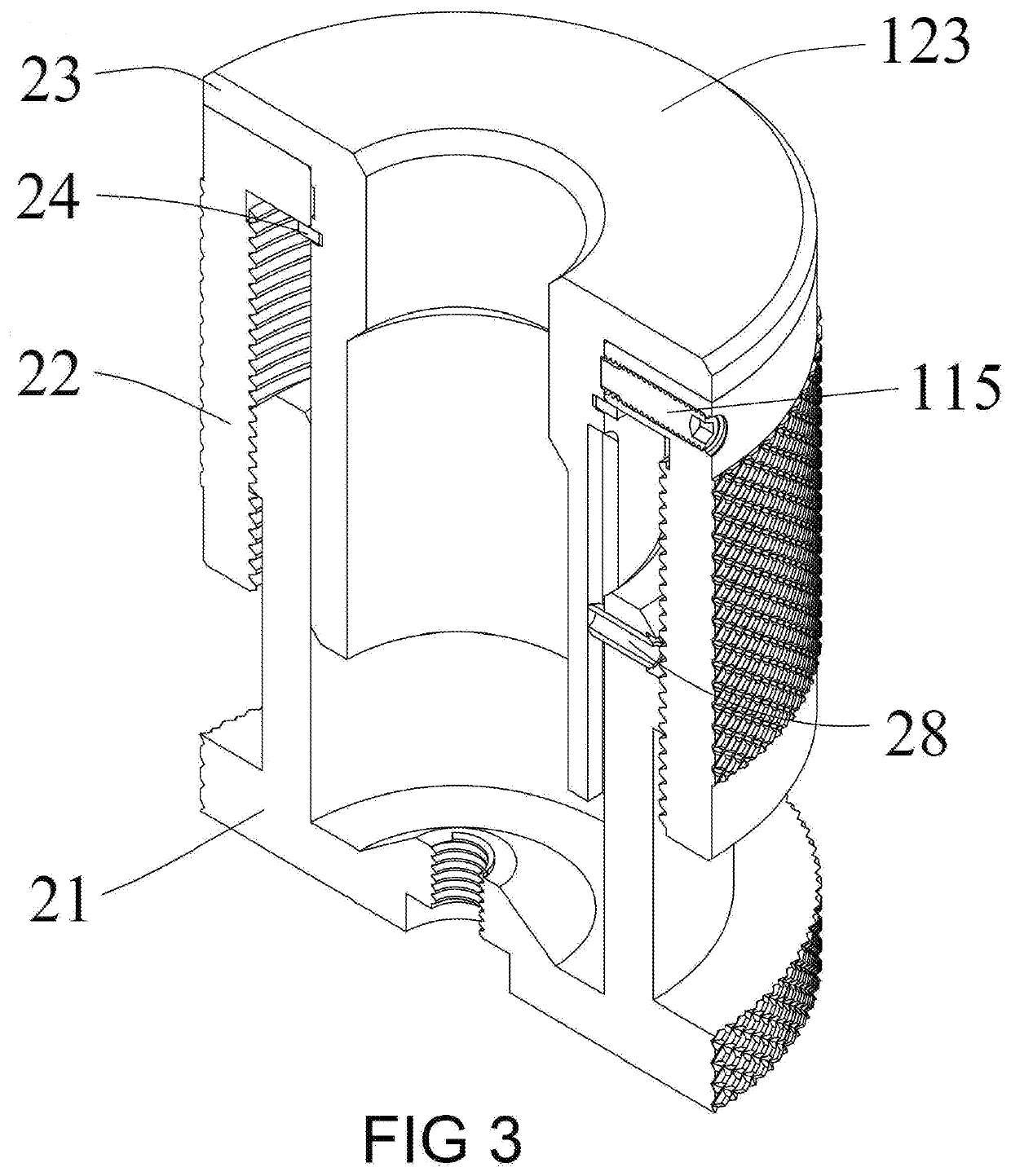
[0023]The base 21 is substantially in a tubular or cylindrical shape, with an outer screw thread portion 32 on upper part of the base 21. The base 21 has a key hole 111 where a key 28 can be inserted through, to reach the vertical straight groove 29 on the cylindrical post 23, as shown in FIGS. 2 and 3.

[0024]The key 28, inserting through key hole 111 and reaching the vertical straight groove 29, prevents the cylindrical post 23 from being turned relative to the base 21 while the up-and-down height adjustment is being done by an operator / worker by rotating the cylindrical knob 22.

[0025]The cylindrical knob 22 is also substantially in a tubular or cylindrical shape and is rotatably fitted to the outside of the base 21. The cylindrical knob 22 has an inner screw thread portion 31 m...


PUM


Abstract

Present invention teaches a height adjustable rest having four main parts: a base, a cylindrical knob, a cylindrical post and a snap ring. The cylindrical post has a vertical straight groove to guide the up-and-down height adjustment when the knob is turned relative to the base. The base holes and the knob holes, along with the corresponding rods, provide increased torque when larger and / or heavier workpiece is being supported. The matching inner thread portion (on the inside of the cylindrical knob) and the outer thread portion (on the outside of the base) is a desired feature to make the product less susceptible to damages or work debris compared to other products with exposed threads.

Description

FIELD AND BACKGROUND OF THE INVENTION[0001]Present invention disclosed and claimed a height adjustable rest that can be used on a welding table or other surfaces similar to a welding table to support work objects.[0002]Available products on the market are either difficult to operate because of insufficient torque when dealing with large / heavy work pieces or that the turning threads on the products get damaged easily due to the exposed design.[0003]Present invention overcomes such deficiencies by the structure that generates greater torque when setting the desired height and makes the threads into an internal feature not subject to damaging force or debris.[0004]An earlier height adjustable rest was shown in U.S. Pat. No. 9,827,636 ('636 Patent), with overlapping ownership with the present invention. The earlier model is different from the invention disclosed herein in significant ways.[0005]The snap ring (element 24) in the earlier model is located at the top portion of the post (FI...

Claims


Application Information

Patent Timeline
IPC IPC(8): B23K37/053B23K37/04
CPCB23K37/0536B23K37/0452B23K37/0461B23K37/04
Inventor TSUI, GARYZHU, DAQING
Owner VALTRA
Learn More