Image processing apparatus, image pickup apparatus, and control method of image processing apparatus
a technology of image processing and image pickup, which is applied in the direction of color television details, television system details, television systems, etc., can solve the problems of difficult application of techniques and temporary disappearance of targeted objects, and achieve the effect of preventing the loss of an image pickup opportunity
- Summary
- Abstract
- Description
- Claims
- Application Information
AI Technical Summary
Benefits of technology
Problems solved by technology
Method used
Image
Examples
first embodiment
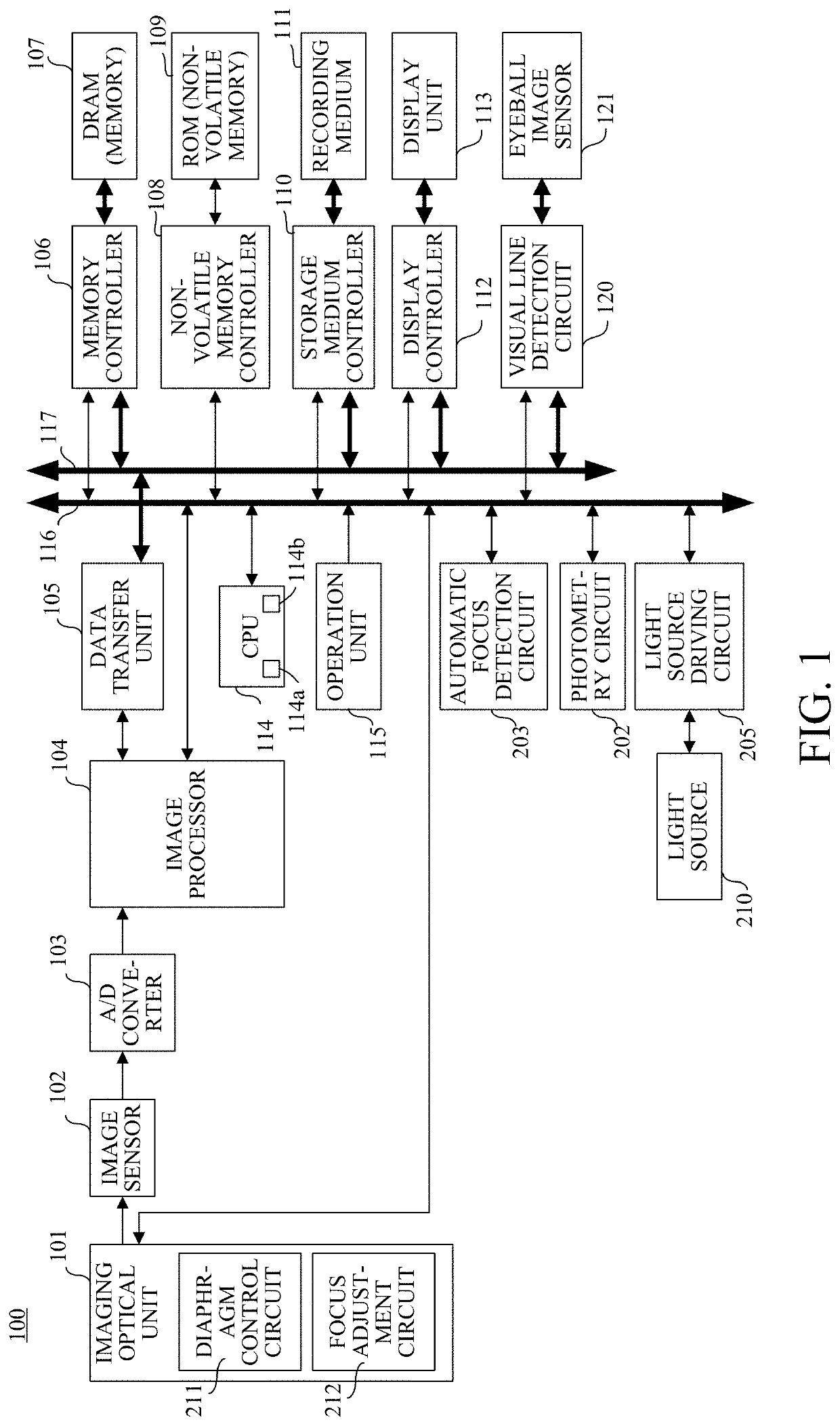
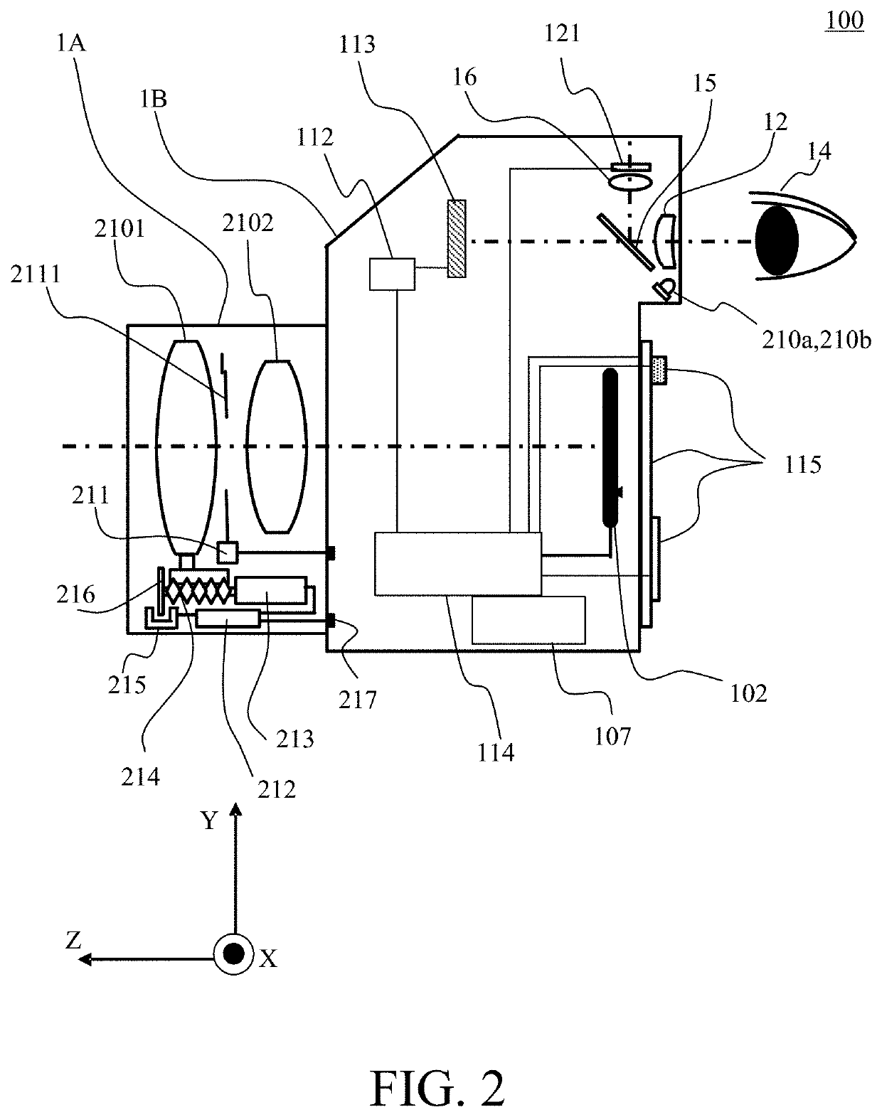
[0034]First, a description will be given of an image pickup apparatus (image processing apparatus) according to a first embodiment of the present invention with reference to FIGS. 1 and 2. FIG. 1 is a block diagram illustrating a digital camera 100 as an image pickup apparatus. FIG. 2 is a sectional view illustrating the digital camera 100. In FIG. 1 and FIG. 2, corresponding elements are represented by same reference numerals.
[0035]In FIG. 1, the imaging optical unit 101 includes an optical system as an image pickup optical system that includes a plurality of lens units having a focus lens and an image stabilization lens, a diaphragm, and the like. The imaging optical unit 101 includes a diaphragm control circuit 211 and a focus adjustment circuit 212. At a time of image pickup, the imaging optical unit 101 adjusts focus with the focus adjustment circuit 212, adjusts an exposure with the diaphragm control circuit 211, performs image stabilization, etc., and forms an optical image o...
second embodiment
[0064]Next, a description will be given of a second embodiment of the present invention with reference to FIGS. 8 and 10A to 10C. FIG. 8 is a flowchart illustrating a control method according to this embodiment. FIGS. 10A to 10C are schematic diagrams each illustrating a display screen of the display unit 113 according to this embodiment. Configurations of a digital camera according to this embodiment are the same as those of the digital camera 100 described in the first embodiment, and thus the description thereof will be omitted.
[0065]First, in step S801, the CPU 114 determines whether or not the image pickup assist button of the operation unit 115 is pressed and the image pickup assist operation (image pickup assist control) start instruction is input. When the image pickup assist operation start instruction is not input, step S801 is repeated. On the other hand, when the image pickup assist operation start instruction is input, the process proceeds to step S802. The CPU 114 meas...
third embodiment
[0071]Next, a description will be given of a third embodiment of the present invention with reference to FIGS. 9 and 10A to 10C. FIG. 9 is a flowchart illustrating a control method according to this embodiment. Each of FIGS. 10A to 10C is a schematic diagram illustrating a display screen of the display unit 113 according to this embodiment. Configurations of a digital camera according to this embodiment is the same as those of the digital camera 100 described in the first embodiment, and thus the description thereof will be omitted. The flowchart of FIG. 9 includes the same processing as that in the flowchart of FIG. 8 described in the second embodiment, and thus a description of the same processing will be omitted.
[0072]Step S901 is the same as step S801 in FIG. 8. After start of image pickup assist operation is determined in step S901, the process proceeds to step S902. In step S902, the CPU 114 starts measuring a time it takes for an angle of view frame 1000 at a focal length of ...
PUM
 Abstract
Description
Claims
Application Information
 - R&D
- Intellectual Property
- Life Sciences
- Materials
- Tech Scout
- Unparalleled Data Quality
- Higher Quality Content
- 60% Fewer Hallucinations
Browse by: Latest US Patents, China's latest patents, Technical Efficacy Thesaurus, Application Domain, Technology Topic, Popular Technical Reports.
© 2025 PatSnap. All rights reserved.Legal|Privacy policy|Modern Slavery Act Transparency Statement|Sitemap|About US| Contact US: help@patsnap.com


