Automatic nut tapping equipment

a tapping equipment and nut technology, applied in the field of tapping equipment, can solve the problems of affecting the accuracy of tapping, and the expansion of the hole during the tapping process, and achieve the effects of high torsional rigidity, convenient calibration, and easy assembly and positioning

Active Publication Date: 2021-08-05
NAT SUN YAT SEN UNIV
View PDF0 Cites 3 Cited by
  • Summary
  • Abstract
  • Description
  • Claims
  • Application Information

AI Technical Summary

Benefits of technology

[0007]The object of the present disclosure is to provide an automatic nut tapping equipment in which the tapping of the nut is completed by a nut clamping mechanism moving back and forth in coordination with a tap rotating mechanism. The tap is rigidly clamped by the tap rotating mechanism, and the back and forth movement of the tap is not required. The center axis of the tap is precisely aligned with the center axis of a rigid clamping member of the tap rotating mechanism and the tap has a high torsional rigidity. In this way, during the nut tapping process, the tap vibration and the hole expansion caused by the tap vibration do not occur. During the tapping, the nut is restricted from rotating and be axially moved automatically with the rotation of the tap without a precise control process to be needed, then a nut with a high-quality internal thread can be completed. A mold is driven to move back and forth toward the tap by a linear moving mechanism, and when the nut is moved to the last pitch of cutting edge on the tap, the tap reversely rotates to prevent a secondary tapping. Because the rotary motion is independent of the linear motion, to replace the mold and to align with the tap are easy, and calibration is convenient. Therefore, when the nut or the tap is changed to another specification, the assembly and the positioning are easy, and which are suitable for mass production. The feeding and the conveying are performed by mechanical mechanisms, and the automatic discharging is performed by a L-shaped lever. Therefore, the present disclosure provides an automatic nut tapping equipment, which has the advantages of high rigidity, high accuracy, and easy calibration.
[0014]As described above, in the present disclosure, the nut clamping mechanism is driven to reciprocate in the same axial through the axial transmission mechanism, and during the reciprocating movement, the nut tapping is completed, and, that is, the internal thread is formed in the nut. Besides, the feeding and discharging of the nut are performed by the L-shaped lever and the push rod coupled with the L-shaped lever, wherein the pushrod can stop the dropping of another to-be-tapped nut during the tapping. Because the tap does not reciprocate and the tapped nut does not pass through the tap shank, the tap is prevented from being tilted, and the accuracy of the nut tapping is effectively improved. Furthermore, the tap does not reciprocate, the tapped nut does not pass through the tap shank, and the length of the tap shank can be shortened and the shaft diameter thereof can be greater. In this way, a higher torsional rigidity is generated during the tapping, thereby the vibration of the tap is avoided / reduced. The shorter and thicker tap shank has high torsional rigidity, such that the rotation delay caused by the rotation deformation can be avoided / reduced and the accuracy of the tapping also can be improved. During the tapping, the nut does not need to completely disengage from the tap but maintain overlapping the last pitch of cutting edge on the tap, and then the tap reversely rotates and the nut retracts to prevent secondary tapping.

Problems solved by technology

Therefore, when a rotation of a tapping process is processed, the tap is tilted and vibrated, thereby resulting in a hole expansion during the tapping process.
Then, when the nut enters the thread of tapping, the tap shank vibrates, thereby affecting the accuracy of the tapping.
The tilted tap results in vibration during a rotation, such that the accuracy of the tapping is affected.
During the tapping process, the tap is affected by the torsional rigidity of the tap shank, which causes the irregularity in the internal thread of the nut.
Once there is an error in the center-welding process, the accuracy of the tapping for the nut is greatly affected.
In addition, during the upward and downward movement of the tap, the downward speed of the tap is not consistent with the upward speed of the tap, the internal thread is damaged.

Method used


Image

  • Automatic nut tapping equipment
  • Automatic nut tapping equipment
  • Automatic nut tapping equipment

Examples


Embodiment Construction

[0023]In the following detailed description of the preferred embodiments, reference is made to the accompanying drawings which form a part hereof, and in which is shown by way of illustrating specific embodiments in which the disclosure may be practiced. In this regard, directional terminology, such as “top”, “bottom”, “front”, “back”, “left”, “right”, “inside”, “outside”, “side”, etc., is used with reference to the orientation of the figure(s) being described. As such, the directional terminology is used for purposes of illustration and is in no way limiting.

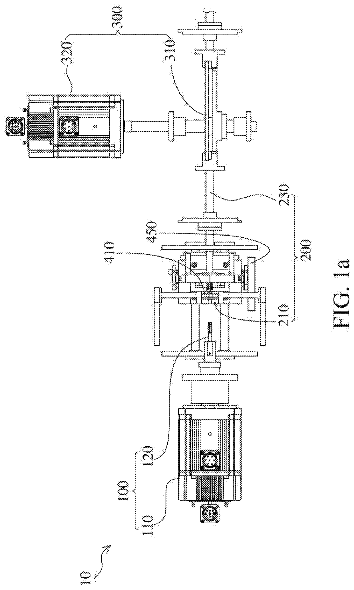
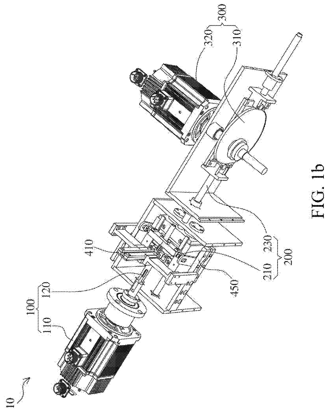
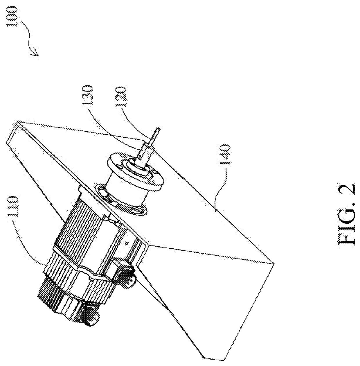
[0024]Please refer to FIG. 1a to FIG. 5. FIG. 1a is a schematic top view of an automatic nut tapping equipment according to an embodiment of the present disclosure. FIG. 1b is a schematic perspective view of the automatic nut tapping equipment in the embodiment of FIG. 1. FIG. 2 is a schematic perspective view of a tap rotating mechanism in the embodiment of FIG. 1b. FIG. 3a is a schematic perspective view of a nut clamping mec...


PUM

PropertyMeasurementUnit
diameteraaaaaaaaaa
lengthaaaaaaaaaa
lengthaaaaaaaaaa

Abstract

An automatic nut tapping equipment is provided. The automatic nut tapping equipment includes a tap rotating mechanism, a nut clamping mechanism, an axial transmission mechanism, and a nut placing slot. The tap rotating mechanism includes a tap rotary motor and a tap, wherein the tap is driven by the tap rotary motor. The nut clamping mechanism includes a clamping assembly and a sliding rail, wherein the clamping assembly is disposed on the sliding rail and is configured for clamping a to-be-tapped nut to restrict the to-be-tapped nut from rotating. The axial transmission mechanism controls the clamping assembly to axially translate one pitch in response to the tap rotating one revolution, such that a forward nut-tapping motion and a backward nut-retracting motion are performed by the nut clamping mechanism. The nut placing slot is configured to arrange and control the dropping of another to-be-tapped nut.

Description

CROSS REFERENCE TO RELATED APPLICATIONS[0001]This application claims the priority of Taiwan Patent Application No. 109103231, filed on Feb. 3, 2020, titled “AUTOMATIC NUT TAPPING EQUIPMENT”, and the disclosure of which is incorporated herein by reference.FIELD OF INVENTION[0002]The present disclosure relates to the field of tapping equipment, and more particularly, to an automatic nut tapping equipment.BACKGROUND OF INVENTION[0003]In the existing floating nut tapping equipment, the tap is welded on the tap shank. The tap constantly rotates in one direction to tap the nut, and then the tapped nut passes through the tap shank and withdraws the tap shank, such that a continuous tapping process is achieved. There is a gap between the tap shank and the hole of the nut. Take M8×1.25 nut as an example. The diameter of the hole of the nut is ϕ6.84, the diameter of the tap shank is ϕ6.1, and therefore, the gap is 0.74 mm. The length of the tap shank is 200 mm, and the distance between each s...

Claims


Application Information

Patent Timeline
Patent Type & Authority Applications(United States)
IPC IPC(8): B23G1/18
CPCB23G1/185Y10T408/47B23Q5/225
Inventor TSAY, DER-MINHWANG, GUAN-SHYONGLIN, TSUNG-CHUNCHEN, WEI-MING
Owner NAT SUN YAT SEN UNIV
Why Eureka
Try Eureka