Method and device in nodes used for wireless communication
a wireless communication and node technology, applied in power management, signalling characterisation, transportation and packaging, etc., can solve the problem that the psfch format 0 with single symbol may not be enough to support a detection, and achieve the effect of improving system efficiency, reducing the probability of correct reception of psfch through selection of different psfch formats, and reducing the degradation of reception performance of psfch receivers
- Summary
- Abstract
- Description
- Claims
- Application Information
AI Technical Summary
Benefits of technology
Problems solved by technology
Method used
Image

Examples
embodiment 1
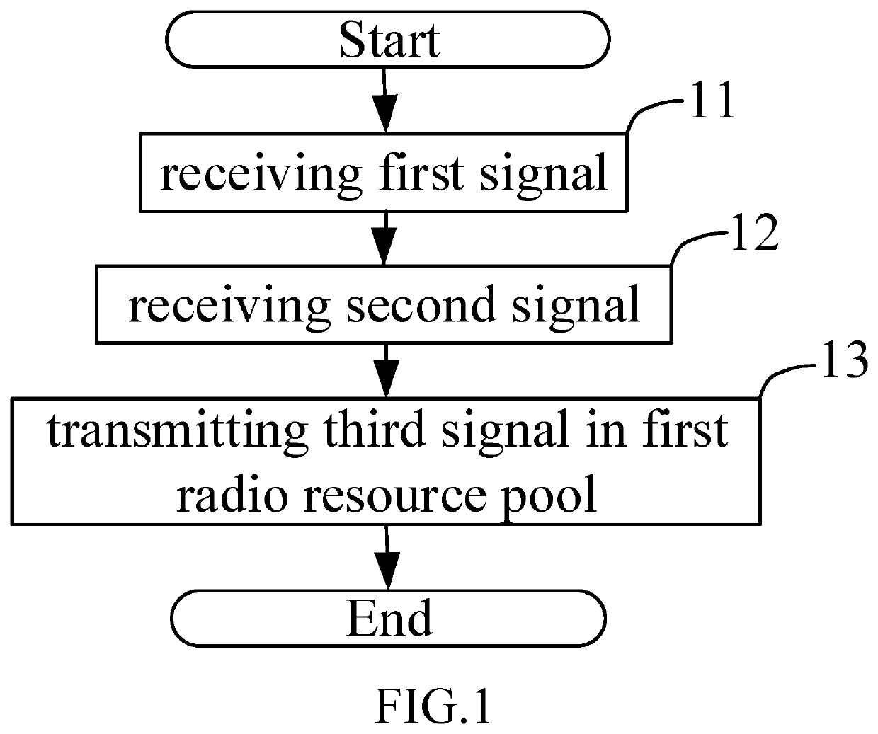
[0081]Embodiment 1 illustrates a processing flowchart of a first node according to one embodiment of the present disclosure, as shown in FIG. 1.
[0082]In Embodiment 1, the first node in the present disclosure receives a first signal in step 11; receives a second signal in step 12; and transmits a third signal in a first radio resource pool in step 13.
[0083]In Embodiment 1, the first signal is used for determining first information, the first information being related to channel quality between the first node and a transmitter of the first signal; the second signal is used for determining second information, the second information being related to channel quality between a transmitter of the second signal and the first node; the transmitter of the first signal is different from the transmitter of the second signal; the first information and the second information are used together for determining a magnitude of time-domain resources occupied by the third signal.
[0084]In one embodiment...
embodiment 2
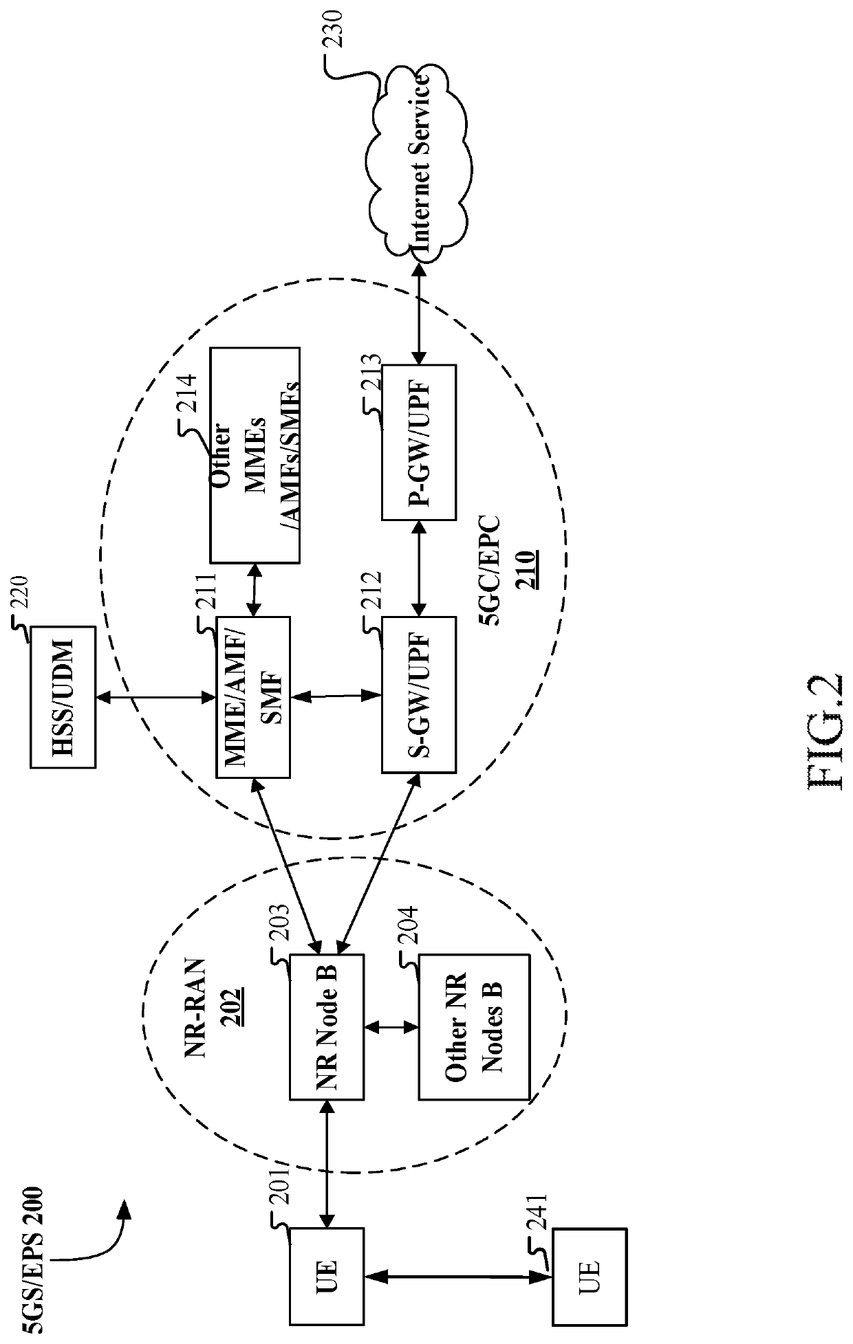
[0167]Embodiment 2 illustrates a schematic diagram of a network architecture according to the present disclosure, as shown in FIG. 2.
[0168]FIG. 2 illustrates a network architecture 200 of 5G NR, Long-Term Evolution (LTE) and Long-Term Evolution Advanced (LTE-A) systems. The 5G NR or LTE network architecture 200 may be called a 5G System (5GS) / Evolved Packet System (EPS) 200 or other appropriate terms. The 5GS / EPS 200 may comprise one or more UEs 201, a UE 241 in Sidelink communications with the UE 201, an NG-RAN 202, a 5G Core Network / Evolved Packet Core (5GC / EPC) 210, a Home Subscriber Server (HSS) / Unified Data Management (UDM) 220 and an Internet Service 230. The 5GS / EPS 200 may be interconnected with other access networks. For simple description, the entities / interfaces are not shown. As shown in FIG. 2, the 5GS / EPS 200 provides packet switching services. Those skilled in the art will readily understand that various concepts presented throughout the present disclosure can be exte...
embodiment 3
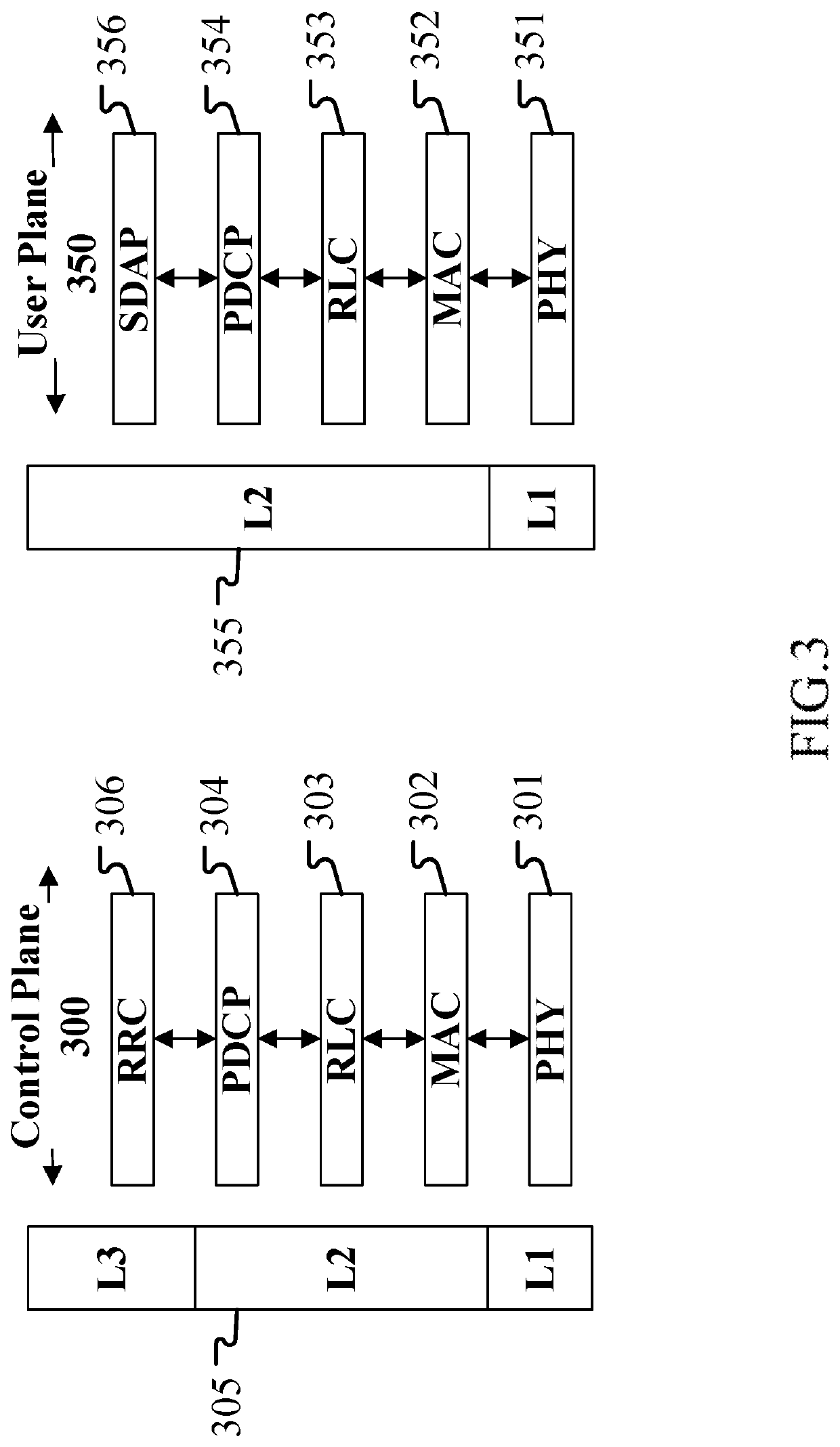
[0185]Embodiment 3 illustrates a schematic diagram of a radio protocol architecture of a user plane and a control plane according to one embodiment of the present disclosure, as shown in FIG. 3.
[0186]Embodiment 3 illustrates a schematic diagram of an example of a radio protocol architecture of a user plane and a control plane according to one embodiment of the present disclosure, as shown in FIG. 3. FIG. 3 is a schematic diagram illustrating an embodiment of a radio protocol architecture of a user plane 350 and a control plane 300. In FIG. 3, the radio protocol architecture for a first communication node (UE, a RSU in gNB or V2X) and a second communication node (gNB, a RSU in UE or V2X), or between two UEs is represented by three layers, which are a layer 1, a layer 2 and a layer 3, respectively. which are a layer 1, a layer 2 and a layer 3, respectively. The layer 1 (L1) is the lowest layer and performs signal processing functions of various PHY layers. The L1 is called PHY 301 in ...
PUM
 Abstract
Description
Claims
Application Information
 - R&D
- Intellectual Property
- Life Sciences
- Materials
- Tech Scout
- Unparalleled Data Quality
- Higher Quality Content
- 60% Fewer Hallucinations
Browse by: Latest US Patents, China's latest patents, Technical Efficacy Thesaurus, Application Domain, Technology Topic, Popular Technical Reports.
© 2025 PatSnap. All rights reserved.Legal|Privacy policy|Modern Slavery Act Transparency Statement|Sitemap|About US| Contact US: help@patsnap.com