Loudpseakers

a loudspeaker and chassis technology, applied in the field of loudspeakers, can solve the problems of reducing the effectiveness of the chassis assembly (usually a steel yoke) on amplifying the coil inductance, and achieve the effects of improving sound quality, increasing axial thickness, and increasing resistan

Active Publication Date: 2021-07-22
GP ACOUSTICS INT
View PDF0 Cites 1 Cited by
  • Summary
  • Abstract
  • Description
  • Claims
  • Application Information

AI Technical Summary

Benefits of technology

The patent describes an improved design for a loudspeaker that achieves better sound quality. The design includes voice coils that overlap in use, which allows for increased movement and improved sound quality. The design also reduces the effectiveness of the chassis assembly on amplifying the coil inductance, resulting in improved performance. A cylindrical spacer made of non-magnetic material helps to address inductance effects and reduce self and mutual inductance of the voice coils. Overall, this design provides a better listening experience for the user.

Problems solved by technology

The magnetic circuit in this mirrored coaxial array has two gaps and consequently is rather higher reluctance than a conventional motor circuit and this helps to reduce the effectiveness of the chassis assembly (usually a steel yoke) on amplifying the coil inductance.

Method used


Image

  • Loudpseakers
  • Loudpseakers
  • Loudpseakers

Examples


Embodiment Construction

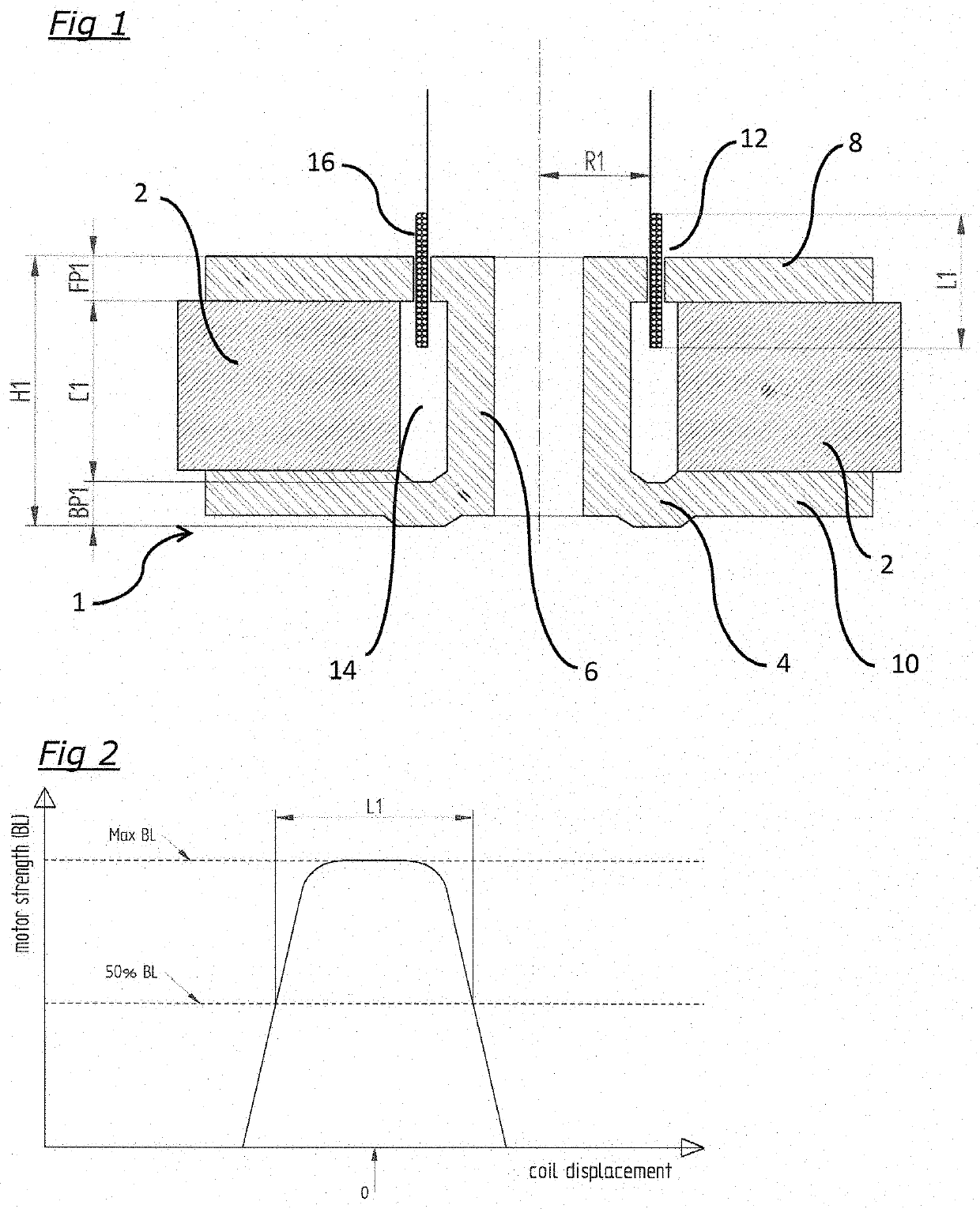
[0021]FIG. 1 shows a conventional over-hung ring-magnet motor system 1. Normally two of these are placed back to back when used in a reaction-force cancelling / vibration-cancelling arrangement (as described in US 2014 / 211963). An annular magnet 2 surrounds a steel yoke 4 which is in the form of a central cylinder 6 with front and rear end plates 8, 10. There is a magnetic gap formed by a circular hole 12 in the front end plate 8, and the hole 12 leads directly to an axially-extending gap 14 between the magnet 2 and the cylindrical part 6 of the yoke 4. A voice coil 16 carrying a varying electric current reciprocates in the magnetic gap 12. The voice coil 16 is mounted at its outer end (the upper end as shown in the drawing) to a diaphragm (not shown) and the reciprocation of the voice coil causes the diaphragm to vibrate, creating acoustic waves as is well-known in the art. In use, the voice coil moves between a negative excursion (when the voice coil is displaced downwardly in the d...


PUM


Abstract

A loudspeaker comprising two acoustic diaphragms mounted to face in axially-opposed directions, two voice coils each having an axis and an axial length and being configured to reciprocate along its axis to drive one of the diaphragms, the axes being substantially parallel and both axes passing through both diaphragms, and at least one magnet forming part of a chassis assembly configured to provide two axially-extending gaps, one for each of the voice coils to reciprocate within, wherein the at least one magnet and the chassis assembly are adapted so that magnetic flux flows across the gaps in opposite directions, and wherein when in use the diaphragms are at their predetermined maximum negative excursions the voice coils overlap in the axial direction by between 10% and 90% of their average axial length, and wherein when in use the diaphragms are in a relaxed position, between their maximum negative and positive excursions, the voice coils do not overlap in the axial direction.

Description

FIELD OF THE INVENTION[0001]The present invention relates to loudspeakers, and in particular to mirrored coaxial acoustic arrays with a nested motor structure.BACKGROUND ART[0002]The structure and operation of moving coil loudspeaker drive units is well known. A vibration diaphragm is attached to a coil of wire known as a voice coil, and the voice coil is placed in a magnetic field usually provided by one or more permanent magnets. By passing an alternating current through the voice coil, a force is induced and the diaphragm can be made to vibrate and so radiate acoustic waves.[0003]What is sometimes not appreciated is that the force induced in the voice coil also gives rise to an unintentional reactive force on the motor system, following Newton's third law of motion. The mechanical vibration resulting from the reactive force on the motor is transmitted via the driver chassis and can excite the walls of a loudspeaker enclosure; in many loudspeaker systems this form of excitation is...

Claims


Application Information

Patent Timeline
Patent Type & Authority Applications(United States)
IPC IPC(8): H04R9/06H04R9/02
CPCH04R9/063H04R9/025H04R9/045H04R9/06H04R2209/041H04R1/2873H04R2499/11H04R2209/026H04R3/12H04R9/046H04R9/02
Inventor OCLEE-BROWN, JACK ANTHONYSPEAR, CHRISTOPHER
Owner GP ACOUSTICS INT
Why Eureka
Try Eureka