
Structure of coils for a wireless charger

a technology of coils and wireless chargers, applied in the direction of electrical apparatus construction details, inductances, transportation and packaging, etc., can solve the problems of heat dissipation of wireless chargers, and achieve the effects of reducing the size of wireless chargers, and sustaining stress

Pending Publication Date: 2021-07-15
CYNTEC
View PDF4 Cites 0 Cited by
  • Summary
  • Abstract
  • Description
  • Claims
  • Application Information

AI Technical Summary

Benefits of technology

The present invention is about a wireless charger with a metallic housing that helps sustain stress and protect the charging coils. It also includes a fan to create airflows in multiple directions for better heat dissipation. This design helps improve the functionality and reduce the size of the wireless charger.

Problems solved by technology

As charging for consumer and automotive devices become more and more popular, however, the there are some restrictions in placing an electronic device over the coils of a wireless charger for charging the electronic device.
In addition, as speed becomes more and more important, the heat dissipation of the wireless charger also becomes an issue.

Method used


Image

  • Structure of coils for a wireless charger
  • Structure of coils for a wireless charger
  • Structure of coils for a wireless charger

Examples


Embodiment Construction

[0044]It is understood that the following disclosure provides many different embodiments, or examples, for implementing different features of the invention. Specific examples of devices and arrangements are described below to simplify the present disclosure. These are, of course, merely examples and are not intended to be limiting. For example, the formation of a first feature over or on a second feature in the description that follows may include embodiments in which the first and second features are formed in direct contact, and may also include embodiments in which additional features are formed between the first and second features such that the first and second features are not in direct contact. In addition, the present disclosure may repeat reference numerals and / or letters in the various examples. This repetition is for the purpose of simplicity and clarity and does not in itself dictate a relationship between the various embodiments and / or configurations discussed.

[0045]The...


PUM

PropertyMeasurementUnit
structureaaaaaaaaaa
conductiveaaaaaaaaaa
metallicaaaaaaaaaa

Abstract

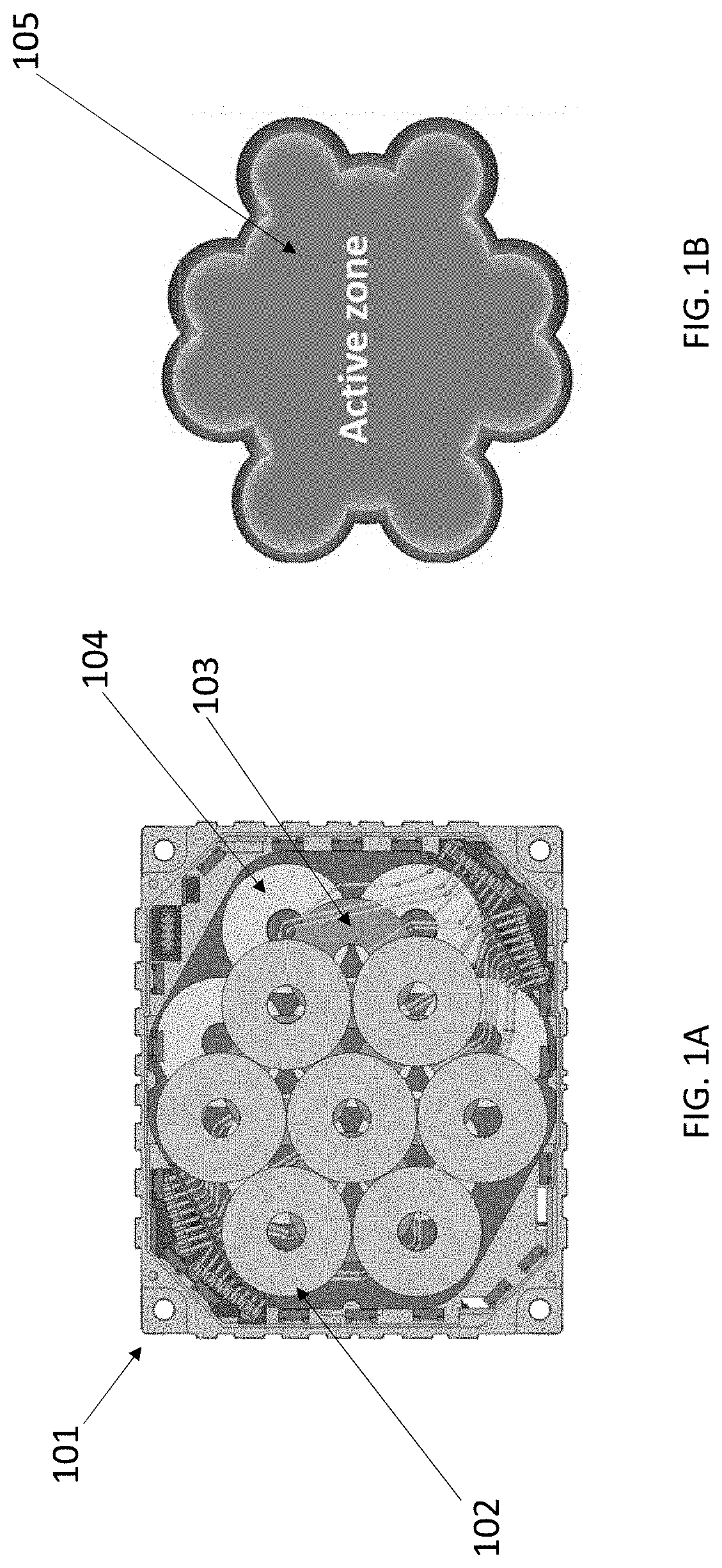
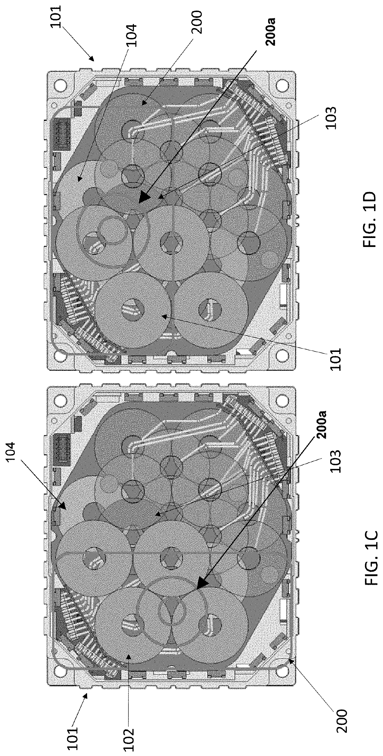
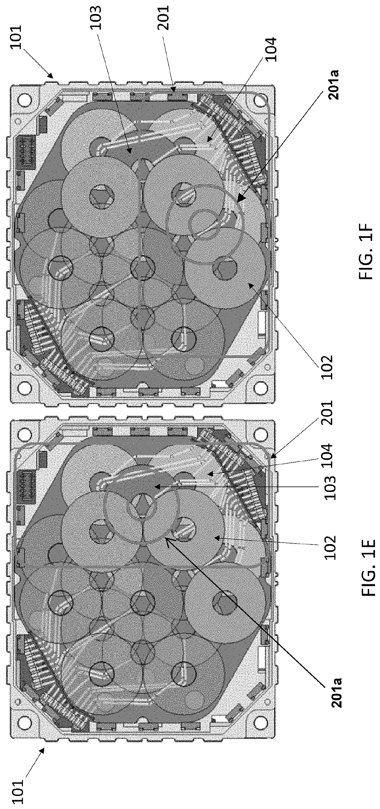
A structure of coils for a wireless charger comprises a plurality of coils, wherein the plurality of coils are stacked into a plurality of layers of coils with each layer comprising at least two coils, wherein at least two electronic devices are capable of being placed over the plurality of coils for charging the at least two electronic devices.

Description

CROSS-REFERENCE TO RELATED APPLICATIONS[0001]This application claims the benefit of U.S. Provisional Application Ser. No. 62 / 960,700 filed on Jan. 14, 2020 and U.S. Provisional Application Ser. No. 63 / 088,431 filed on Oct. 6, 2020, the entirety of each Provisional application is incorporated by reference herein.BACKGROUND OF THE INVENTIONField of the Invention[0002]The invention relates to a structure of coils, and in particular, to a structure of coils for charging an electronic device.Description of the Related Art[0003]As charging for consumer and automotive devices become more and more popular, however, the there are some restrictions in placing an electronic device over the coils of a wireless charger for charging the electronic device. In addition, as speed becomes more and more important, the heat dissipation of the wireless charger also becomes an issue.[0004]Accordingly, the present invention proposes a better solution to overcome the above-mentioned problems.SUMMARY OF THE...

Claims


Application Information

Patent Timeline
Patent Type & Authority Applications(United States)
IPC IPC(8): H01F38/14H02J7/02H02J50/10H02J50/40H02J7/00H01F27/32H01F27/28H01F27/34
CPCH01F38/14H02J7/02H02J50/10H02J50/402H04M1/0202H01F27/327H02J7/0042H01F27/288H01F27/346H02J7/0013H01F5/02H02J7/00H05K7/20136H01F2005/027H01F27/025H01F27/2804H01F2027/2809H01F27/402H01F27/366
Inventor CHIU, KUAN YUYU, CHING HSIANGCHUNG, MIN-FENG
Owner CYNTEC
Learn More