Lighting system

Active Publication Date: 2021-07-15
SIGNIFY HOLDING B V
View PDF0 Cites 0 Cited by
  • Summary
  • Abstract
  • Description
  • Claims
  • Application Information

AI Technical Summary

Benefits of technology

The patent text describes a lighting system for shop windows that has several features. The first feature is that the lighting unit is mounted on an elongated carrier with a unique orientation, creating a unique light beam with a fixed orientation. This allows for the creation of a unique light patch on the target area, such as a window. The second feature is that the lighting device is offset from the target area in a specific direction, making it easier to control the illumination. The third feature is that the control unit has a display or camera to show the lighting pattern in real-time, making it easier to adjust the light intensity based on the ambient light levels. Overall, this lighting system provides a more efficient and effective way to illuminate shop windows.

Problems solved by technology

From research it is known that with known lighting devices and lighting systems setting the lighting in a shop window scene is often considered as a hassle for the shop's personal or the visual merchandiser who has to do the decoration and the lighting.
(1) Often there is limited space in the shop window since most space is occupied by the displayed models and products. Therefore, standing in the shop window is risky, a small mistake in moving around can cause the complete scene to be disturbed.
(2) Another disadvantage is that the spots for the shop window illumination are normally installed at a higher position, out of reach for arms, which means that a ladder is needed to aim the spots. This brings again the danger to disturb the scene and the risk of falling down resulting in injuries for the staff personal of the shop.
(3) Next to the limited space it is not possible to judge the (modelling) result of the lighting (play of light and shadow) as a result of the position of the spots and the aiming since the person who is doing this is too close to the scene to (over)see the visual end result as it is visible from the street. For the best result one should be standing outside in front of the shop window and instruct someone else to get the perfect positioning and aiming of the spots to make the lighting scene as wanted.
(4) Furthermore there is the problem of over or under lighting the scene. In daytime one has to bring light on the scene with a high intensity to reduce the disturbing reflections in the window glass caused by the daylight (reflecting from opposite surfaces). This is normally done by using narrow beam spots with a high intensity to increase the brightness on the display. But there are big differences in lighting levels depending on the time, season and weather conditions. So normally the lighting level is installed to work under the most difficult lighting circumstances (so a high day light level measured by clear sky at 12.00 hours in summertime). This makes that often the display is over lit (when the daylight conditions are lower) and it consumes a lot of energy. At night time this is not needed and only a small amount of the light would enable to make beautiful more balanced lighting scenes adding to the quality of the presentation and saving energy at the same time. In practice it is often found that the same lighting solution is used 24 / 7.
Normally it is not possible to make a scene with moving light unless movable spots are used.
The disadvantage is that dynamic (mechanically moving) products are more sensitive for failures and maintenance as static products.
A lot of people who are doing shop window presentations are not aware of these effects and also often the variety of spots is not available on stock in the store.

Method used


Image

  • Lighting system
  • Lighting system
  • Lighting system

Examples


Embodiment Construction

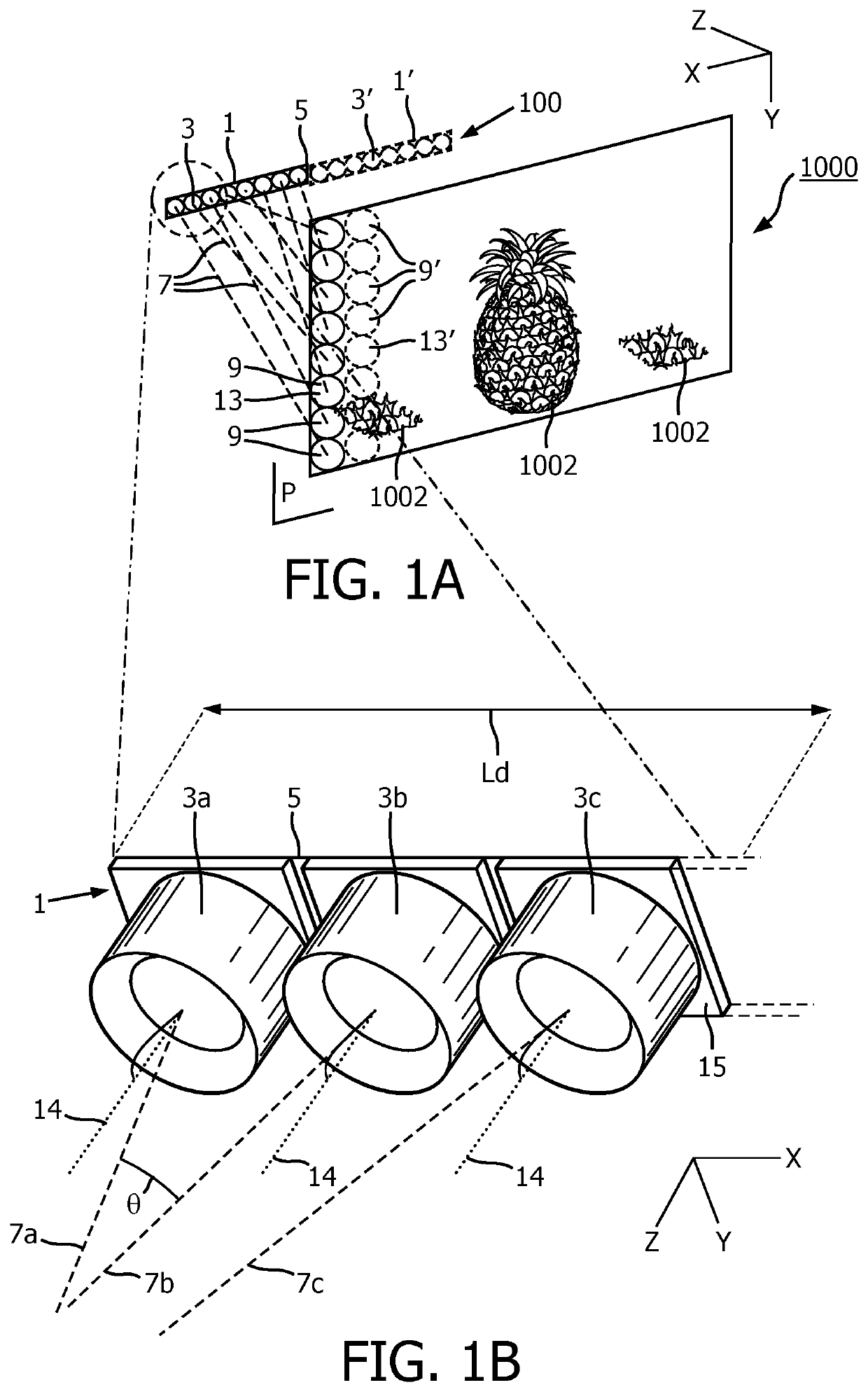
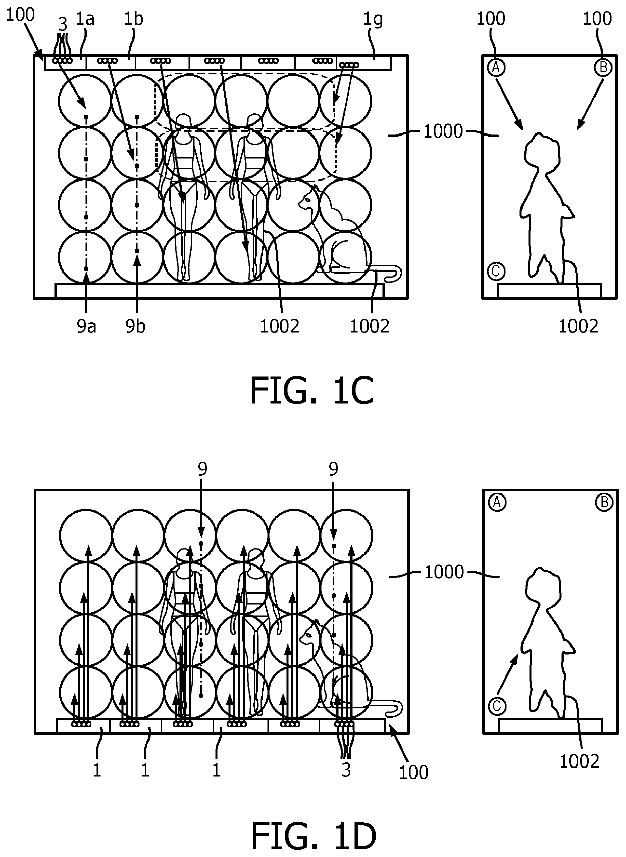
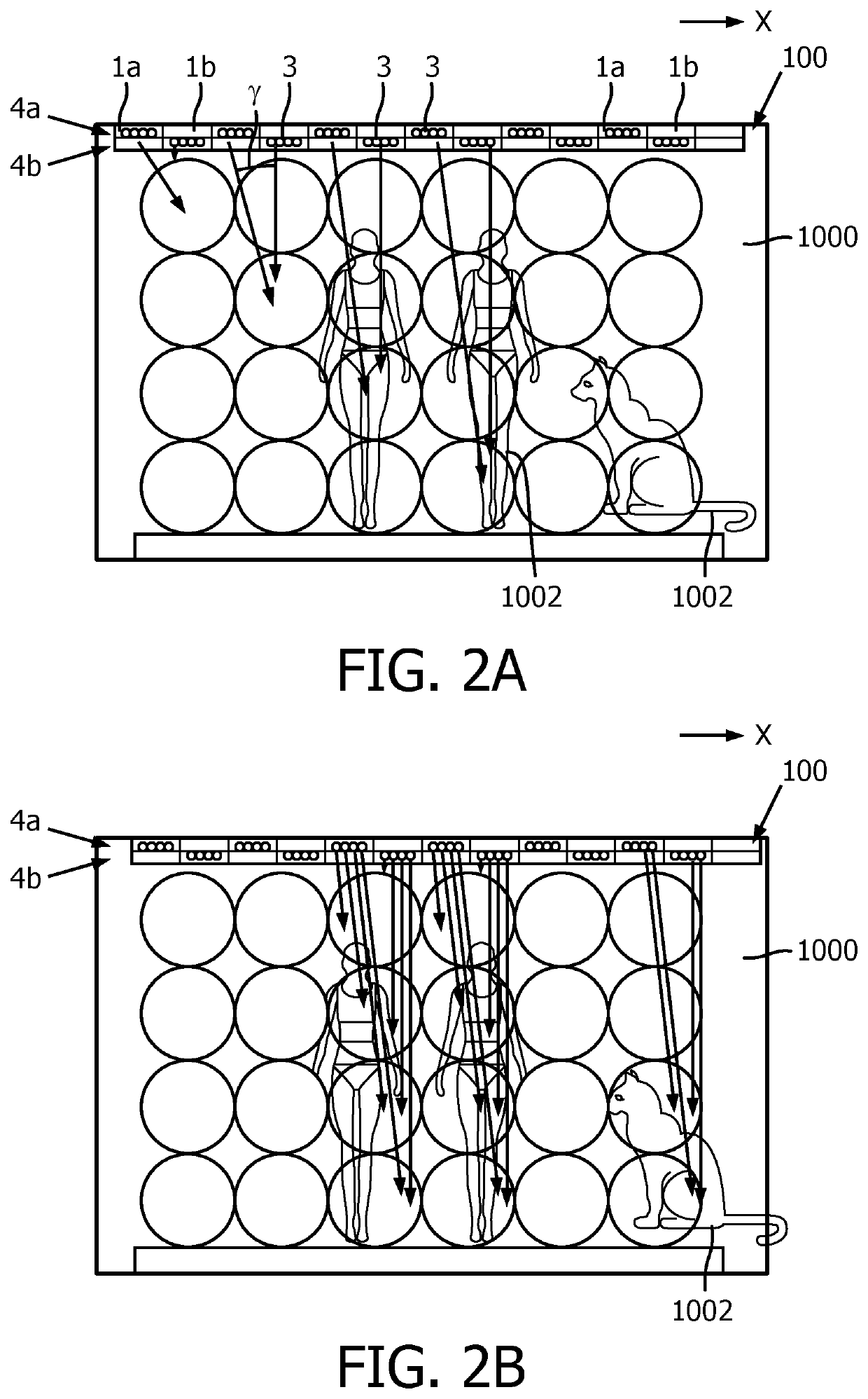
indow 1000 provided with displayed articles 1002 for explaining the principle of the invention. Thereto it shows a first, lighting device 1 comprising a linear row of eight lighting units 3 mounted and extending only in a first direction X on an elongated carrier 5. Alternatively, the lighting device, the carrier and / or the row of lighting devices might have a slightly curved shape, for example over a curvature angle of at the most 30°. Each lighting unit 3 being mounted with a respective, fixed, unique, pre-determined orientation as indicated by a respective optical axis 7. Said first lighting device 1 being configured to directly project on a target area 11, i.e. plane P in which the displayed articles 1002 are located, a first row of light patches 9, said plane P extending in said first direction X and in a second direction Y transverse, i.e. Δ≈90° however slightly deviations are possible, to said first direction (when directions XYZ are according to an orthogonal Cartesian Coord...


PUM


Abstract

The invention relates to a lighting device, a lighting system and a lighting method. The lighting device comprises a row of lighting units mounted in a first direction X on an elongated carrier wherein each lighting unit is mounted with a respective, fixed, unique, pre-determined orientation. Said lighting device is configured to directly project on a target plane P a row of light patches, said plane P extending in said first direction X and in a second direction Y transverse to said first direction. Said row of light patches extends in the second direction and wherein said lighting device is offset out of said plane P in a third direction Z. The lighting system comprises at least a first and at least one second lighting device substantially lying in line in the length direction. Optionally said first and at least one second lighting device may extend in two or three parallel rows. Said lighting system further optionally comprises a control unit for individual control / addressing of the lighting units of the at least first and further lighting device.

Description

FIELD OF THE INVENTION[0001]The invention relates to a lighting system.BACKGROUND OF THE INVENTION[0002]From research it is known that with known lighting devices and lighting systems setting the lighting in a shop window scene is often considered as a hassle for the shop's personal or the visual merchandiser who has to do the decoration and the lighting. It usually involves number of disadvantages:[0003](1) Often there is limited space in the shop window since most space is occupied by the displayed models and products. Therefore, standing in the shop window is risky, a small mistake in moving around can cause the complete scene to be disturbed.[0004](2) Another disadvantage is that the spots for the shop window illumination are normally installed at a higher position, out of reach for arms, which means that a ladder is needed to aim the spots. This brings again the danger to disturb the scene and the risk of falling down resulting in injuries for the staff personal of the shop.[00...

Claims


Application Information

Patent Timeline
IPC IPC(8): F21V19/00F21V23/00H05B47/175A47F11/10
CPCF21V19/001F21V23/003F21Y2103/10A47F11/10H05B47/175H05B47/19H05B47/1965F21W2131/405F21S4/28F21Y2113/17F21Y2113/13G09F13/02F21S4/20F21Y2113/10
Inventor VISSENBERG, MICHEL CORNELIS JOSEPHUS MARIEVAN DER POEL, LUCAS LEO DESIRECREUSEN, MARTINUS PETRUS
Owner SIGNIFY HOLDING B V
Why Eureka
Try Eureka