Ejection device and flying body provided with ejection device
a technology of ejection device and flying body, which is applied in the direction of aircraft, emergency apparatus, transportation and packaging, etc., can solve the problems of preventing the spread of flying objects, reducing and reducing the risk of flying objects falling off, so as to reduce the weight and reduce the ejection speed of ejection objects
- Summary
- Abstract
- Description
- Claims
- Application Information
AI Technical Summary
Benefits of technology
Problems solved by technology
Method used
Image
Examples
first embodiment
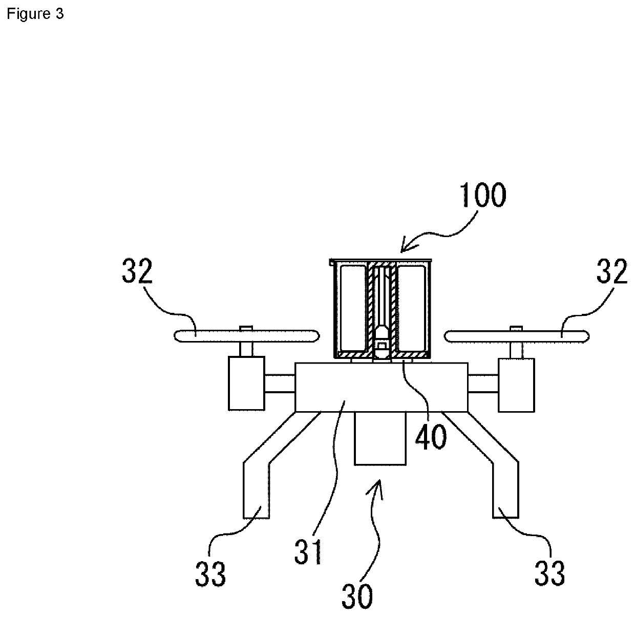
[0066]As shown in FIG. 1, an ejection device 100 according to the present embodiment includes a piston member 10 which is a sliding member, a cylinder 14 which accommodates the piston member 10 and is provided with a hole portion 13 for allowing the piston member 10 to project outward (upward in FIG. 1) during operation, a push-up member 15 pushed up in one direction (upward in FIG. 1) by the piston member 10, an ejected object 16 pushed up while being supported by the push-up member 15, a gas generator (such as a micro gas generator) 17 as a power source that moves the piston member 10 in the cylinder 14, and a bottomed cylindrical container 18 which accommodates the piston member 10, the cylinder 14, the push-up member 15, the ejected object 16, and the gas generator 17.
[0067]In the present embodiment, the ejected object 16 is a parachute or a paraglider. The gas generator 17 is disposed below a main body portion 11 of the piston member 10, which will be described later, in a stat...
second embodiment
[0080]Next, an ejection device according to the second embodiment will be described. In the present embodiment, components with the same last two digits as those in the above first embodiment are the same as those described in the first embodiment unless otherwise described, and therefore the description thereof is omitted. The same applies to the drawings in each of the following embodiments. In FIG. 4(b), the same applies to components with the same last two digits as those in FIG. 4(a). Since components not particularly described are the same as those in the first embodiment, and the description and illustration will be omitted. In each of the following embodiments, as a general rule, differences from the first embodiment will be mainly described.
[0081]As shown in FIG. 4(a), in an ejection device 200 of the present embodiment, at portions of a substantially circular support portion 220, which face each other in a radial direction, projecting portions 230 which respectively projec...
third embodiment
[0084]Next, an ejection device according to the third embodiment will be described. As shown in FIG. 5, in an ejection device 400 of the third embodiment, a driving piston member 430 which has a main body portion 431 and a rod-shaped portion 432, and is a driving sliding member, which moves a piston member 410 in a non-contact (or contact) manner, is provided in a cylinder 414. A container 418 has a plurality of vent holes 424 near a lower end of a position lower than a position of a support portion 420, and the lower end is fixed to an airframe 445 of a flying object. A lower end of the cylinder 414 is fixed to the airframe 445 of the flying object.
[0085]According to this configuration, by disposing the piston member 410 such that the piston member 410 can move only when a considerable pressure is applied, when a gas generator 417 is operated, a considerable amount of compressed air can be accumulated between the driving piston member 430 and the piston member 410. Then, the compre...
PUM
 Abstract
Description
Claims
Application Information
 - R&D
- Intellectual Property
- Life Sciences
- Materials
- Tech Scout
- Unparalleled Data Quality
- Higher Quality Content
- 60% Fewer Hallucinations
Browse by: Latest US Patents, China's latest patents, Technical Efficacy Thesaurus, Application Domain, Technology Topic, Popular Technical Reports.
© 2025 PatSnap. All rights reserved.Legal|Privacy policy|Modern Slavery Act Transparency Statement|Sitemap|About US| Contact US: help@patsnap.com


