
Data transmission system and method in physical network separation environment

a data transmission system and physical network technology, applied in the direction of electric digital data processing, instruments, computing, etc., can solve the problems of difficult to track and manage the data input to the control network in the future, difficult to process tasks in real time, and significantly inefficient data transmission methods using optical discs to the critical information infrastructure network, etc., to achieve automatic transmission of data files, increase the effect of data transmission consumption time and increase the security threa

Active Publication Date: 2021-07-01
KOREA ELECTRIC POWER CORP
View PDF0 Cites 0 Cited by
  • Summary
  • Abstract
  • Description
  • Claims
  • Application Information

AI Technical Summary

Benefits of technology

The present invention is for a method that automatically transmits data files in a physical network separation environment, using an optical disc drive or USB drive. The method allows for faster data transmission, improved functioning of ICT facilities and enhancement of security, by addressing issues and vulnerabilities in conventional methods such as constraints on function improvement and inefficient personnel operation. It also enables data connection and additional functions with systems in the intranet, and stores every file introduced into the critical information infrastructure network for easy tracking and management in the future.

Problems solved by technology

As described above, the data transmission method using the optical disc to the critical information infrastructure network is a significantly inefficient method because it requires manual labor.
With the method, a considerable time gap occurs from the time when a need for transmitting data occurs until the time when the data is actually transmitted, and thus it is difficult to process tasks in real time.
Also, it is difficult to track and manage the data input to the control network in the future.
Thus, if a security incident occurs, it may be difficult to know the causes.
This method is a critical barrier to the function and performance improvement of the critical information infrastructure network, resulting in an increase in the risk of occurrence of the security incident and inefficiency in the related personnel operation.
However, physical network separation between the critical information infrastructure network and the intranet causes a data transmission time to be longer.
If a system management staff is absent, it becomes an operation environment where data transmission is impossible, and thus function expansion and maintenance of the critical information infrastructure may be impossible.
The physical network separation causes inefficiency in operation management of the critical information infrastructure installed nationwide and deteriorates the quality of the public service.
Thus, when employing the method using the optical disc, data may not be received on time.
Such a secret communication line may be exposed to cyber infringement even if it is configured temporarily.
Third, the manager of the critical information infrastructure, etc. may work very inefficiently.
Fourth, the likelihood of human security incident increases during the data transmission process.
Also, the location in which the critical information infrastructure is installed is a restricted area.
Even for authorized persons, frequent access to the restricted area may result in an increase of factors in the occurrence of intentional or unintentional access security incidents.
Fifth, when transmitting the file by a human, it is difficult to track and manage the data input to the critical information infrastructure network in the future.
Therefore, when hacking incidents occur, it is nearly impossible to analyze the causing file, and it takes considerable time.

Method used


Image

  • Data transmission system and method in physical network separation environment
  • Data transmission system and method in physical network separation environment
  • Data transmission system and method in physical network separation environment

Examples


Embodiment Construction

b>Hereinbelow, a preferred embodiment of the present invention will be described in detail with reference to the accompanying drawings. However, it should be understood that the embodiment of the present invention may be changed to a variety of embodiments and the scope and spirit of the present invention are not limited to the embodiment described hereinbelow. The embodiment of the present invention described hereinbelow is provided for allowing those skilled in the art to more clearly comprehend the present invention. Therefore, it should be understood that the shape and size of the elements shown in the drawings may be exaggeratedly drawn to provide an easily understood description of the structure of the present invention. The same reference numerals refer to similar elements throughout. In the following description, it is to be noted that when the functions of conventional elements and the detailed description of elements related with the present invention may make the gist of ...


PUM


Abstract

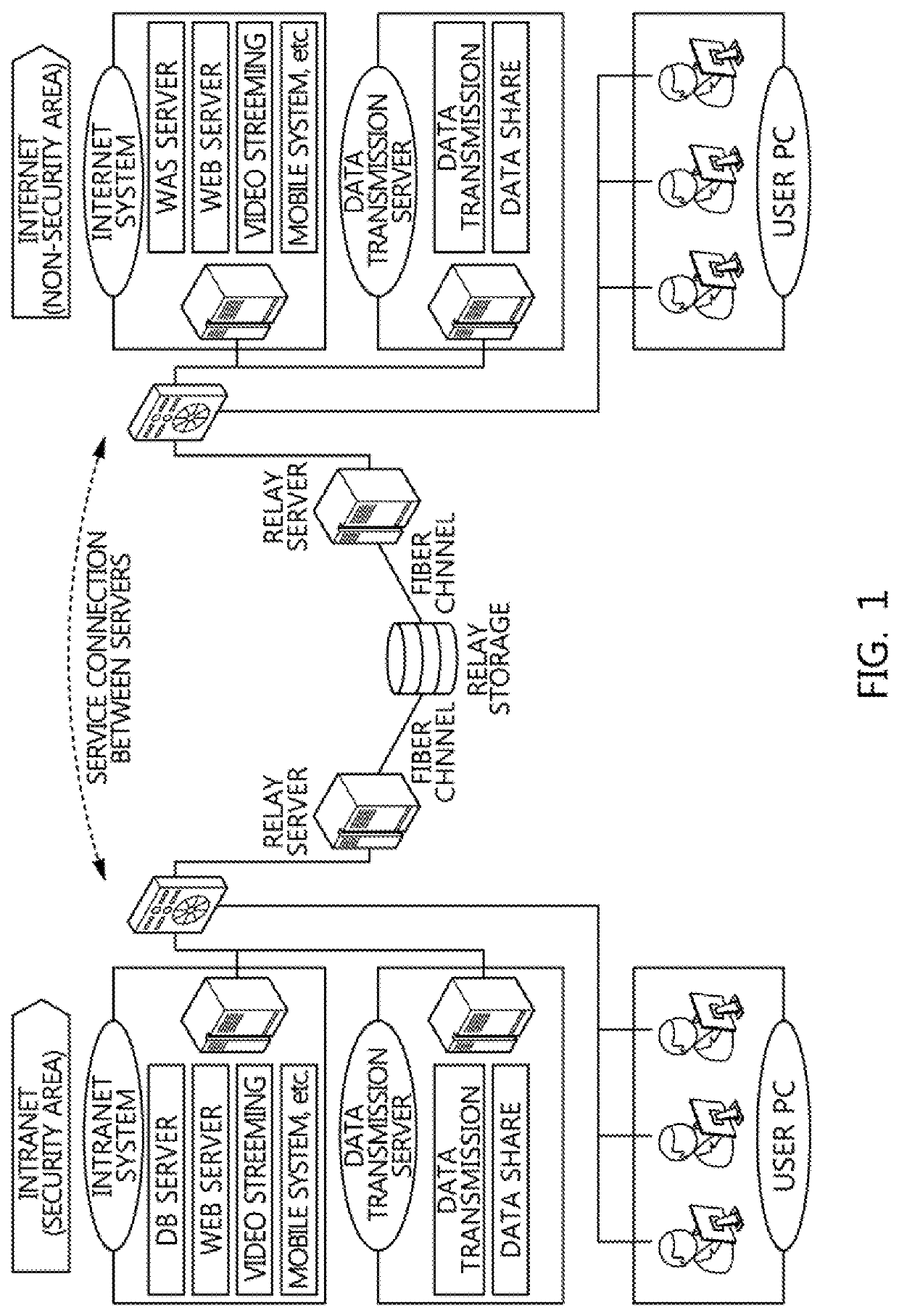
The present invention relates to a data transmission system and method in a physical network separation environment. According to an embodiment of the present invention, the data transmission system includes: a drive device controlling connection switching for one storage medium drive writing or reading a data file on or from a predetermined storage medium; a source-side server executing writing the data file on the storage medium loaded in the storage medium drive, after switching to a connection to the storage medium drive; a clean PC conducting hash value verification and a test for infection of malicious code with respect to the data file that has been written on the storage medium, after switching to a connection to the storage medium drive; and a destination-side server executing reading the tested data file from the storage medium, after switching to a connection to the storage medium drive.

Description

TECHNICAL FIELD[0001]The present invention relates to a data transmission system and method in a physical network separation environment. More particularly, the present invention relates to a data transmission system and method in a physical network separation environment, the system and method enabling an optical disc drive in which an optical disc is loaded or a USB drive in which a USB storage medium is loaded to physically switch so as to transmit a data file between a source-side server, a clean PC, and a destination-side server in order, thereby automatically transmitting the data file in the physical network separation environment.[0002]Also, the present invention relates to a data transmission system and method in a physical network separation environment, the system and method using an automatic optical disc transfer unit to physically transmit an optical disc in an optical disc drive connected to each of a source relay server, a clean PC, and a destination relay server, th...

Claims


Application Information

Patent Timeline
Patent Type & Authority Applications(United States)
IPC IPC(8): G06F21/56G06F13/38G06F21/12
CPCG06F21/566G06F2213/0042G06F21/125G06F13/382G06F21/567G06F21/562G06F21/606H04L63/0218H04L67/06G06F21/56G06F21/64G06F21/85
Inventor KIM, JONG-KWANLEE, SEUNG-YOUNYANG, SEUNG-KWONKIM, MYONG-SOOKIM, DONG-WOOK
Owner KOREA ELECTRIC POWER CORP
Learn More