
Resonance voltage attenuation detection circuit, semiconductor device for switching power, and switching power supply

a detection circuit and attenuation technology, applied in testing circuits, instruments, base element modifications, etc., can solve the problems of large switching noise, large switching loss, pwm control, etc., and achieve small switching loss, small switching noise, and small output voltage and sound noise.

Active Publication Date: 2021-07-01
MITSUMI ELECTRIC CO LTD
View PDF1 Cites 0 Cited by
  • Summary
  • Abstract
  • Description
  • Claims
  • Application Information

AI Technical Summary

Benefits of technology

The invention provides a switching power supply and a semiconductor device for a switching power that have low switching loss, low switching noise, and good power efficiency. The device uses a PWM control and a quasi-resonance control that are switched during normal operation, resulting in a higher average power efficiency and a smaller power supply. This reduces the need for large transformers and parts, making the power supply more compact.

Problems solved by technology

For example, the PWM control has disadvantages of large switching loss, large switching noise and slightly poor power efficiency.
However, the PWM control has small sound noise.
On the other hand, the quasi-resonance control makes sound noise due to bottom skip and can only be operated in a discontinuous current mode.
Therefore, the quasi-resonance control has a disadvantage that a transformer, an output capacitor and other parts need to be larger.
It brings problems such as a larger ripple of the output voltage due to large fluctuation of a switching cycle, and generation of sound noise.

Method used


Image

  • Resonance voltage attenuation detection circuit, semiconductor device for switching power, and switching power supply
  • Resonance voltage attenuation detection circuit, semiconductor device for switching power, and switching power supply
  • Resonance voltage attenuation detection circuit, semiconductor device for switching power, and switching power supply

Examples


first embodiment

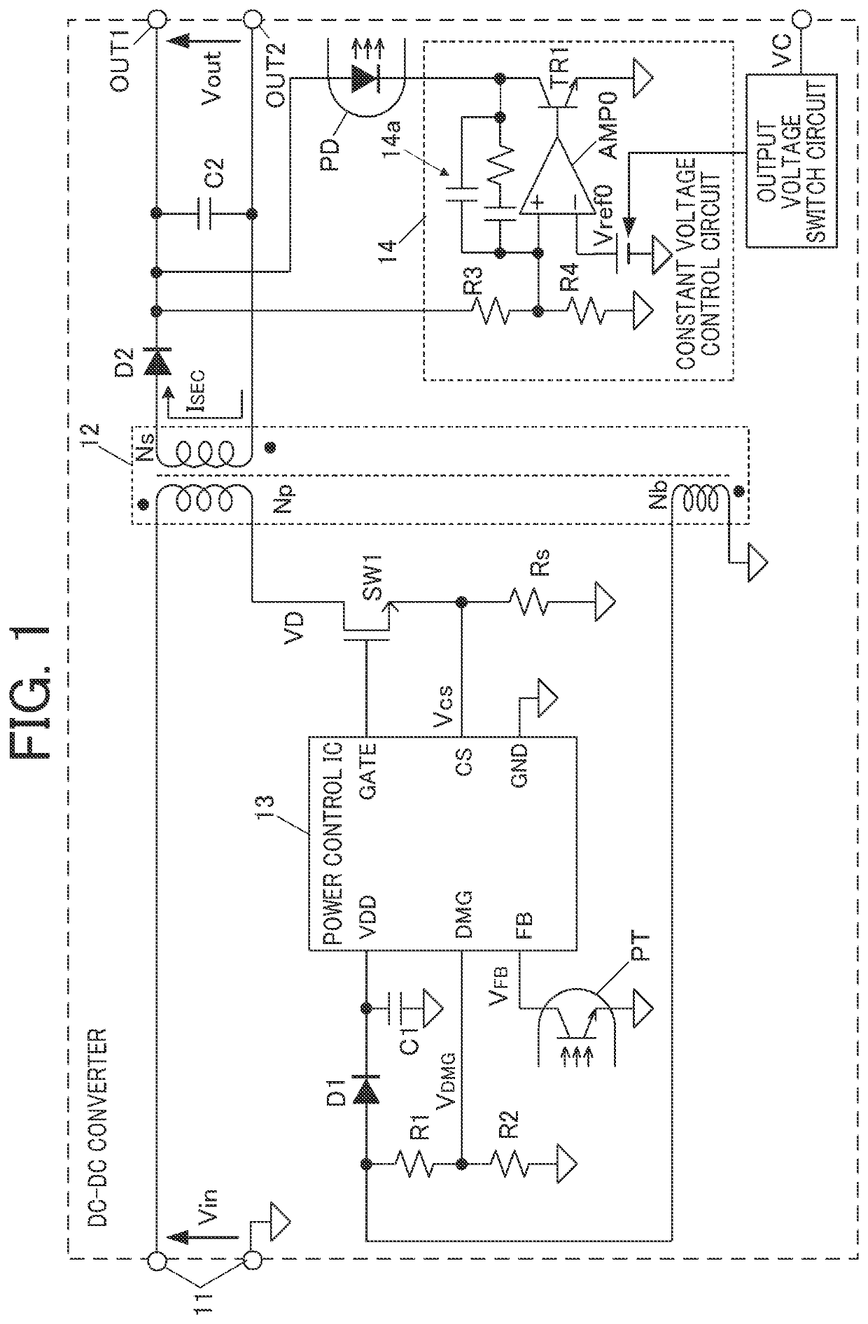
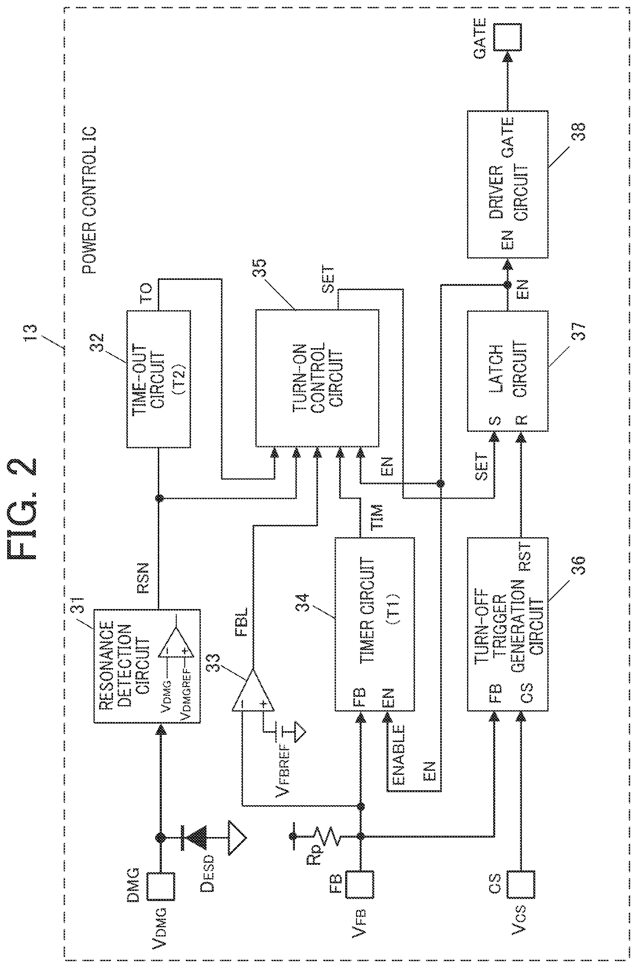
[0158]Configuration of function blocks and functions of the blocks in the first embodiment of the power control IC 13 on the primary side of the power supply in FIG. 1 will be described with reference to FIG. 2 to FIG. 11.

[0159]As shown in FIG. 2, the power-control IC 13 of the embodiment includes:

[0160]a resonance detection circuit 31 having a comparator (voltage comparator circuit) that monitors the voltage VDMG of the external terminal DMG to detect resonance;

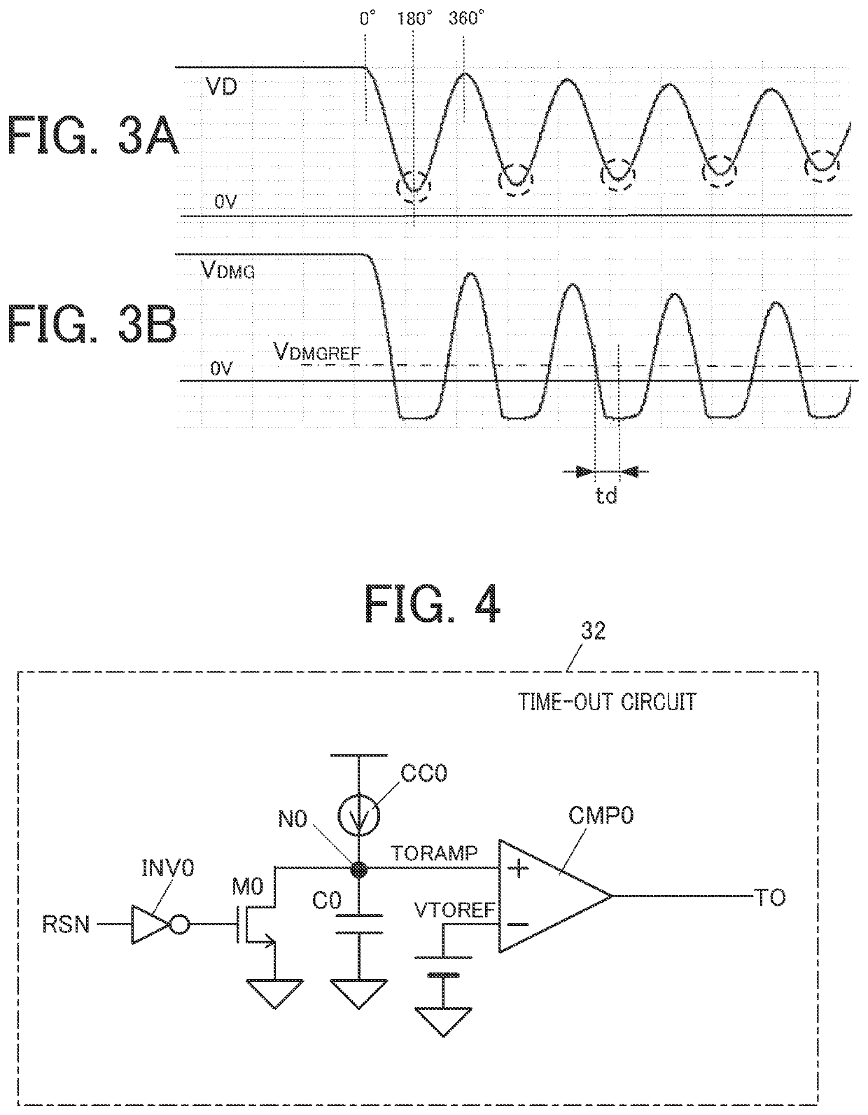
[0161]a time-out circuit 32 that begins clocking in response to detection of resonance and raises an output signal after clocking a predetermined period T2;

[0162]an FB comparator 33 that compares the voltage VFB of the external terminal FB with a predetermined reference voltage VFBREF to determine whether VFB is equal to or less than VFBREF; and

[0163]a timer circuit 34 that generates a switching cycle of the switching element SW1 by clocking a period corresponding to the voltage VFB of the external terminal FB.

[0164]The time...

second embodiment

[0238]FIG. 12 shows configuration of functional blocks of the power control IC 13 of the second embodiment.

[0239]The power control IC of the second embodiment in FIG. 12 has a configuration similar to the one in the power control IC of the first embodiment in FIG. 2. The difference from the power control IC of the first embodiment in FIG. 2 is that the power control IC of the second embodiment does not have the FB comparator 33 in the power control IC of the first embodiment, but has an attenuation detection circuit 39 instead. The attenuation detection circuit 39 monitors the voltage VDMG of the external terminal DMG and detects attenuation of a resonance voltage. Although the power control IC 13 of the second embodiment in FIG. 12 does not have the time-out circuit 32 in the power control IC of the first embodiment, the attenuation detection circuit 39 in the second embodiment has the same function as the time-out circuit 32 of the first embodiment. Therefore, the substantial diff...


PUM

PropertyMeasurementUnit
voltageaaaaaaaaaa
output voltageaaaaaaaaaa

Abstract

A resonance voltage attenuation detection circuit detects attenuation of a resonance voltage of a winding of a transformer. The resonance voltage attenuation detection circuit includes a first voltage comparator circuit and a time-out circuit. The first voltage comparator circuit compares a voltage of the winding with a predetermined first voltage. The time-out circuit performs clocking operation in accordance with an output of the first voltage comparator circuit. The time-out circuit outputs an attenuation detection signal when the time-out circuit has clocked a preset period which is shorter than a time required for a peak voltage of the winding to be attenuated from the first voltage to a predetermined second voltage lower than the first voltage.

Description

CROSS REFERENCE TO RELATED APPLICATION[0001]This application is based upon and claims the benefit of priority under 35 USC 119 of Japanese Patent Application No. 2019-235114 filed on Dec. 25, 2019, the entire disclosure of which, including the description, claims, drawings and abstract, is incorporated herein by reference in its entirety.BACKGROUND OF THE INVENTION1. Field of the Invention[0002]The present invention relates to a resonance voltage attenuation detection circuit, a semiconductor device for a switching power (power control IC), and a switching power supply which detect attenuation of resonance occurring in a winding through which a current flows intermittently.[0003]The present invention particularly relates to:[0004]a power control IC that controls a switching element on a primary side of a DC power supply with a voltage conversion transformer;[0005]a resonance voltage attenuation detection circuit in the power control IC; and[0006]a switching power supply to which the...

Claims


Application Information

Patent Timeline
Patent Type & Authority Applications(United States)
IPC IPC(8): G01R31/62G01R19/165G01R31/14G01R1/20
CPCG01R31/62G01R1/20G01R31/14G01R19/16566H02M3/28H02M3/33523H02M3/33592H02M1/08H02M1/14H02M1/0058Y02B70/10
Inventor ARIMA, SATOSHIMATSUDA, HIROKI
Owner MITSUMI ELECTRIC CO LTD
Learn More