Method and apparatus for heat storage

a technology of heat storage and heat exchanger, which is applied in the direction of fluid heaters, indirect heat exchangers, lighting and heating apparatus, etc., can solve the problems of increasing the cost of stored energy compared to the cost of energy used directly, and most solutions are expensive, so as to achieve efficient heating

Pending Publication Date: 2021-06-24
HELIAC APS
View PDF10 Cites 0 Cited by
  • Summary
  • Abstract
  • Description
  • Claims
  • Application Information

AI Technical Summary

Benefits of technology

[0009]It has been recognized by the present inventors that it is important that the storage system chosen can be charged with thermal energy in an efficient manner that allows maximum heat transfer between the heat source and the heat storage system and minimum losses of heat, and that, similarly, the storage system can be discharged of its stored thermal energy in an efficient manner. In addition, it would be desirable when using a large solid thermal mass to avoid the need to provide complicated-to-manufacture embedded tubing or similar means for distribution of the heat, while also ensuring that the heat distribution within the storage system is even, avoiding the formation of hot zones that are in close contact with the heat source or cold zones that are not in sufficiently close contact with the heat source to be efficiently heated by it. Further, there is a preference for the use of naturally available materials, and / or low-cost materials, and / or locally available materials, and for re-use of materials where possible, especially where the storage system is to be incorporated into a renewable energy generation system such as a solar powered system, a wind-powered system, a wave-powered system or a heat pump system (eg a ground source heat pump or an air source heat pump).

Problems solved by technology

However, most solutions are expensive compared to the amount of energy stored, or have a limited number of operational cycles (charge-discharge), substantially increasing the cost of stored energy compared to energy used directly.

Method used


Image

  • Method and apparatus for heat storage
  • Method and apparatus for heat storage

Examples


example 1

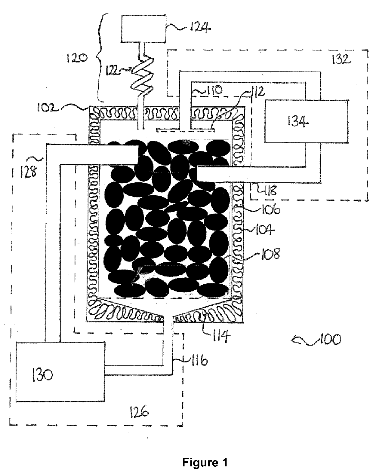
[0138]A concentrated solar power plant delivering thermal oil at 350° C. is used as a heat source. The thermal oil is passed through a counter flow heat exchanger heating and evaporating a heat transfer fluid with normal boiling point 300° C. The internal pressure in the reservoir and connected input / output systems are maintained below 0.01 bar through the use of a vacuum pump with a connection tube that is maintained at ambient temperature. The vapor pressure of the thermal oil at ambient temperature is typically of the order of 10−5 bar, resulting in very low evacuation of heat transfer liquid from the system, while maintaining a low residual air pressure. When the temperature of the heat reservoir is low, the total pressure in the system is low, equal to the vapor pressure of the heat transfer liquid plus the residual air pressure. At this pressure, the heat transfer liquid will evaporate at decreased temperature in the input system, thus able to maintain a relatively low return ...

example 2

[0140]A concentrated solar power plant delivering thermal oil at 350° C. is used as a heat source. The thermal oil is passed through a counter flow heat exchanger heating and evaporating linseed oil with normal boiling point 287° C. The internal pressure in the reservoir and connected input / output systems is reduced to around 0.01 bar prior to charging the reservoir with heat through the use of a vacuum pump with a connection tube that is maintained at ambient temperature. The vapor pressure of the linseed oil at ambient temperature is typically of the order of 10−5 bar, resulting in very low evacuation of heat transfer liquid from the system, while maintaining a low residual air pressure. When the temperature of the heat reservoir is low, the total pressure in the system is low, equal to the vapor pressure of the heat transfer liquid plus the residual air pressure. At this pressure, the heat transfer liquid will evaporate at decreased temperature in the input system, thus able to m...

example 3

[0142]A concentrated solar power plant delivering thermal oil at 350° C. is used as a heat source. The thermal oil is passed through a counter flow heat exchanger heating a heat transfer fluid with normal boiling point 300° C. which is maintained at 5 bar pressure in the said heat exchanger. The heat transfer fluid is heated to 345° C. at 5 bar in the heat exchanger, whereafter it is injected through a pressure reduction valve into the reservoir. The internal pressure in the reservoir and connected input / output systems are maintained below 0.01 bar through the use of a vacuum pump with a connection tube that is maintained at ambient temperature. Upon injection of the superheated heat transfer fluid, it partly evaporates at the reservoir inlet, and subsequently condenses on the coldest part of the reservoir. To prevent ambient air from building up in the reservoir (e.g. entering through small cracks in the encapsulation or leaky joints), a vacuum pump will continuously pump on the ch...


PUM


Abstract

A heat storage reservoir comprising: at least one input inlet for introduction of gaseous heat transfer fluid, or for introduction of superheated liquid heat transfer fluid, into the heat storage reservoir, and at least one liquid recovery system for recovery of liquid heat transfer fluid from the heat storage reservoir; and / or at least one gas outlet for recovery of gaseous heat transfer fluid from the heat storage reservoir, and at least one output inlet for introduction of liquid heat transfer fluid into the heat storage reservoir; and further comprising a volume of solid granular material, to which volume heat is transferred by means of a phase change from gas to liquid of a heat transfer fluid on contact of the heat transfer fluid with the solid granular material, and / or from which volume heat is transferred by means of a phase change from liquid to gas of a heat transfer fluid on contact of the heat transfer fluid with the solid granular material, which volume is in fluid connection with the at least one input inlet and the at least one liquid recovery system, and / or the at least one gas outlet and the at least one output inlet, and a pressure reduction system in fluid connection with the volume of solid granular material, characterized in that the pressure reduction system is arranged to reduce the gas pressure contribution arising from non-condensable species only.

Description

FIELD OF THE INVENTION[0001]The present invention relates to a thermal storage for storing energy for later use, a heat storage reservoir, and a method for storing heat.BACKGROUND OF THE INVENTION[0002]Many energy generation technologies, especially renewable sources such as wind and solar power, deliver energy in a pattern not coincident with the local energy consumption. Therefore, storage of energy for later use is an important aspect of the energy infrastructure. Today, many such technologies do exist, such as chemical batteries and thermal storage solutions. However, most solutions are expensive compared to the amount of energy stored, or have a limited number of operational cycles (charge-discharge), substantially increasing the cost of stored energy compared to energy used directly. Therefore, a solution which is scalable to store large amounts of energy at a low cost with a high number of operational cycles would be advantageous.[0003]FR2981736 describes a heat storage syste...

Claims


Application Information

Patent Timeline
Patent Type & Authority Applications(United States)
IPC IPC(8): F28D20/00
CPCF28D20/0056F28D17/005F28D17/04F24H7/02F24D2200/14Y02B10/20Y02E60/14
Inventor PRANOV, HENRIK
Owner HELIAC APS
Why Eureka
Try Eureka