
Cutting Guide With Protective Insert

a cutting guide and insert technology, applied in the field of cutting guides with protective inserts, can solve the problems of not being able to allow surgeons to be flexible, contribute to the malalignment of the prosthesis, and poor fit between the prosthesis and the resection surfa

Pending Publication Date: 2021-06-24
STRYKER EURO OPERATIONS HLDG LLC
View PDF4 Cites 0 Cited by
  • Summary
  • Abstract
  • Description
  • Claims
  • Application Information

AI Technical Summary

Benefits of technology

This patent is related to a cutting block used in surgical procedures. The cutting block has one or more apertures that allow for the insertion of a sleeve, which is a tool used to make cuts. The apertures are designed to limit the movement of the sleeve, which means that the size, angle, and rotation of the cut are also limited. The cutting block may have multiple apertures that correspond to the location of the cuts needed in the surgery. The instrument that is used with the cutting block guides it so that the sleeve can only be placed in the preoperatively determined locations. This helps to ensure precise and safe surgical procedures.

Problems solved by technology

Oscillating sawblades used for most resections follow the path of least resistance when cutting through bone and deflect in a manner creating variations in the cut surfaces and contributing to prosthesis mal-alignment as well as poor fit between the prosthesis and the resection surfaces.
However, such guides have either not allowed for any flexibility for the surgeon from a preoperative plan at the time of a surgical operation or have not provided sufficient control such that resections have been made that deviated from the preoperative plan.

Method used


Image

  • Cutting Guide With Protective Insert
  • Cutting Guide With Protective Insert
  • Cutting Guide With Protective Insert

Examples


Embodiment Construction

[0038]As used herein, the term “proximal,” when used in connection with a surgical tool or device, or components of a device, refers to the end of the device closer to the user of the device when the device is being used as intended. On the other hand, the term “distal,” when used in connection with a surgical tool or device, or components of a device, refers to the end of the device farther away from the user when the device is being used as intended. As used herein, the terms “substantially,”“generally,”“approximately,” and “about” are intended to mean that slight deviations from absolute are included within the scope of the term so modified.

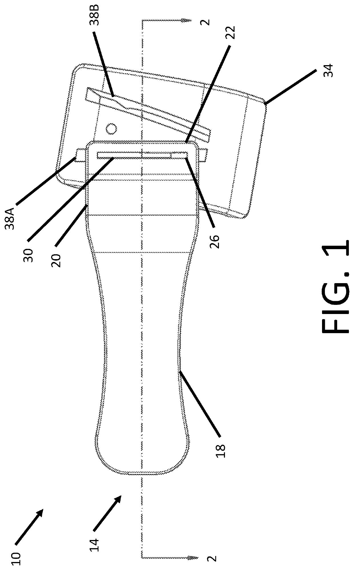
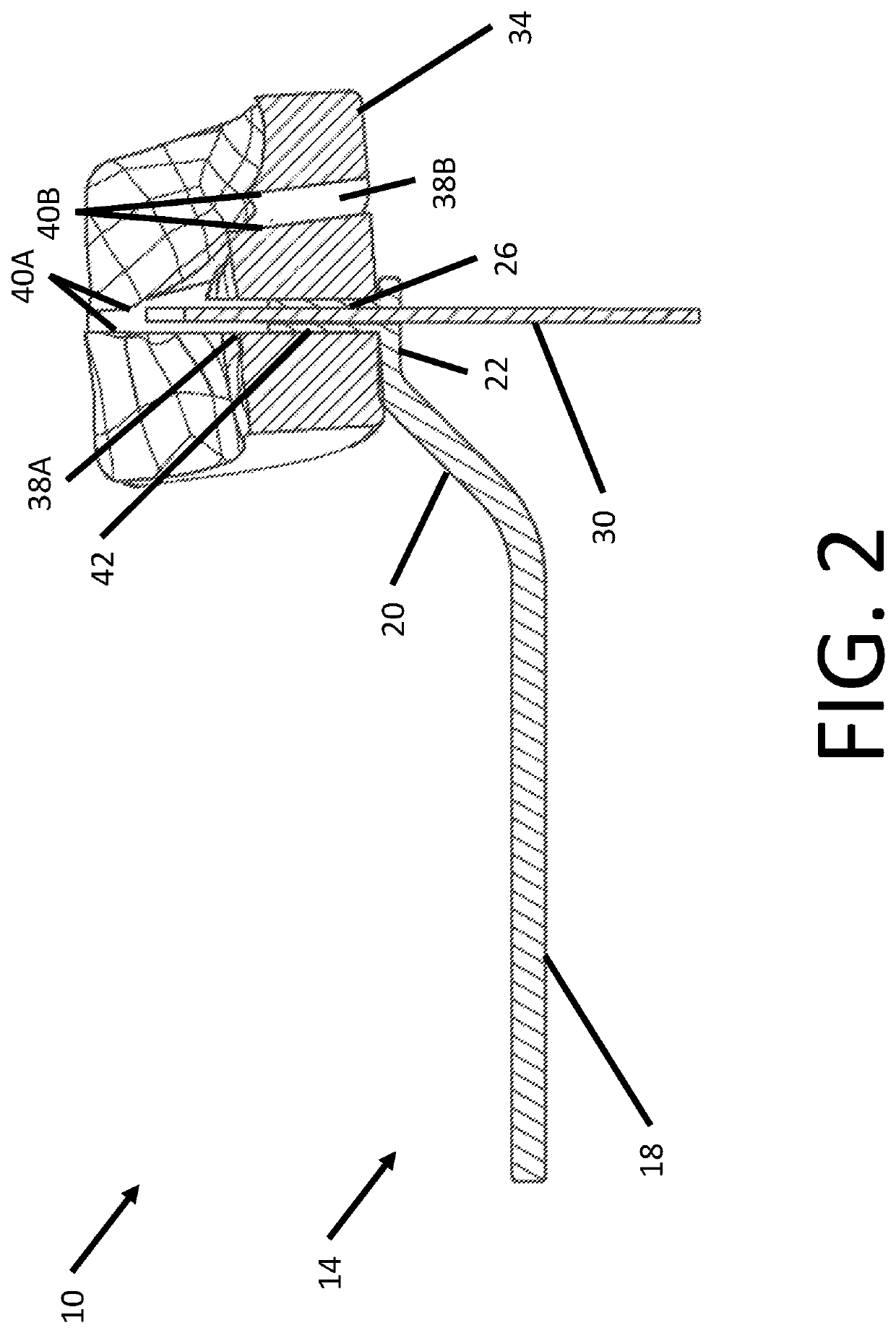
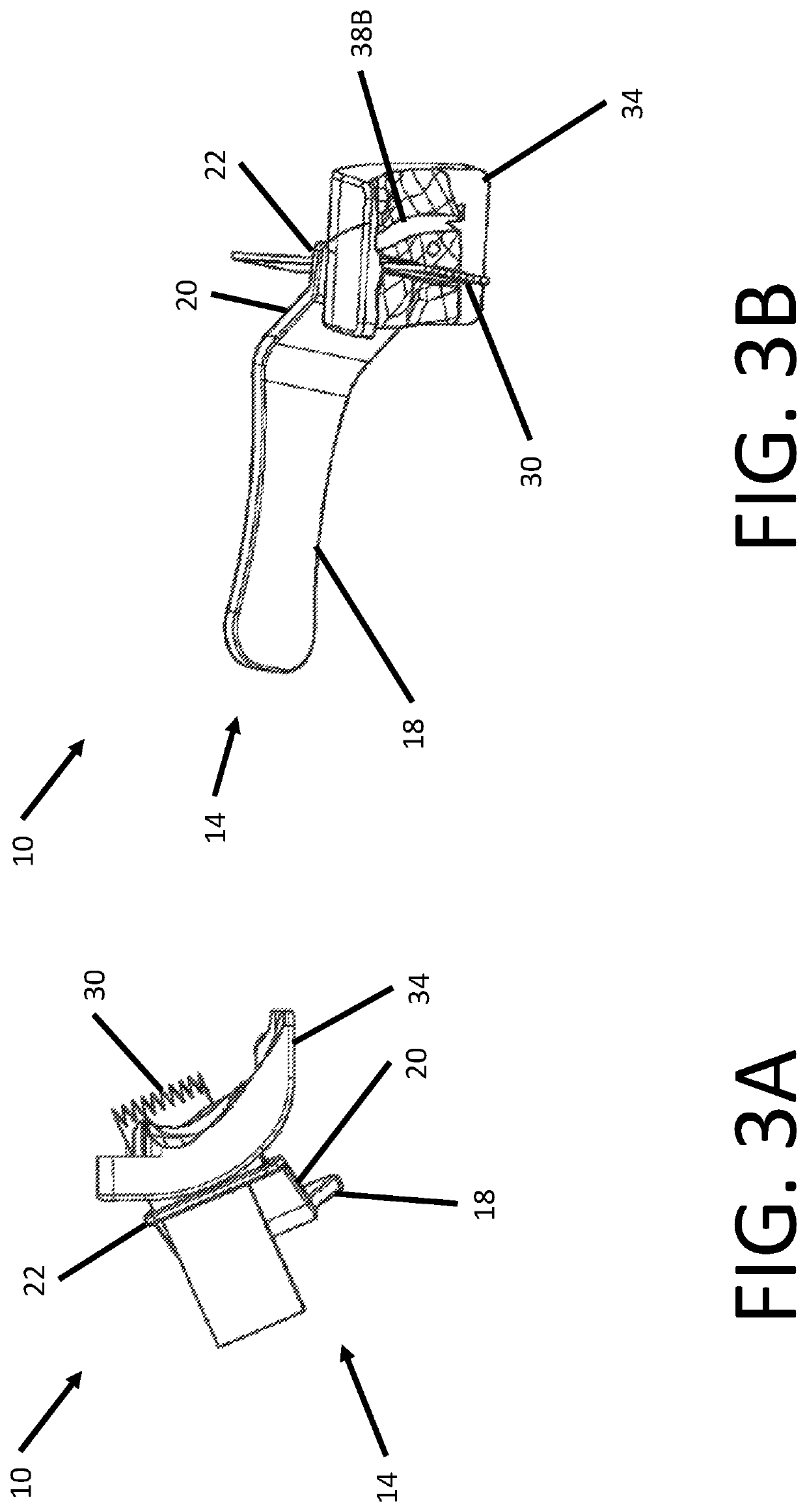
[0039]Referring to FIG. 1, cutting guide system 10 includes instrument 14 and cutting block 34. Instrument 14 includes a handle 18, a head 22, and a neck 20 connecting handle 18 to head 22. Head 22 includes a slot 26 extending in a direction perpendicular to a length of handle 18. A sawblade 30, which in some arrangements may form part of cutt...


PUM


Abstract

A system for guiding a cutting tool in an osteotomy procedure includes a cutting block. The cutting block includes an aperture extending through a thickness of the cutting block and having a length and a width. The width of the aperture is defined between a first interior surface of the cutting block and a second interior surface of the cutting block opposing the first interior surface. The system further includes a sleeve. The sleeve includes a slot configured for receiving a sawblade and configured for insertion into the aperture of the cutting block such that the sleeve contacts either the first interior surface or the second interior surface without contacting the other interior surface.

Description

CROSS REFERENCE TO RELATED APPLICATIONS[0001]The present application claims the benefit of the filing date of U.S. Provisional Patent Application No. 62 / 953,264 filed Dec. 24, 2019, the disclosure of which is hereby incorporated herein by reference.BACKGROUND OF THE INVENTION[0002]Different methods and devices have been developed in the past to enable a surgeon to remove bony material to create specifically shaped surfaces in or on a bone for various reasons such as for the attachment of various devices or objects to the bone. As the ultimate goal of any surgical procedure is to restore the body to normal function, it is critical that the quality, location, and orientation of a surgeon's cut, as well as the quality of the bone at and around the cut are sufficient for achieving proper healing of the body.[0003]These aspects of bone resections are critical to the final location and orientation of any implant and thus play a significant role in the success or failure of any surgery or ...

Claims


Application Information

Patent Timeline
IPC IPC(8): A61B17/17A61B17/16
CPCA61B17/1775A61B17/1633A61B17/151A61B2017/568A61B17/1739A61B17/3439A61B17/152A61B2017/320052
Inventor SINGH, MANOJ KUMARFINKENZELLER, FELIX
Owner STRYKER EURO OPERATIONS HLDG LLC
Learn More