Push switch
- Summary
- Abstract
- Description
- Claims
- Application Information
AI Technical Summary
Benefits of technology
Problems solved by technology
Method used
Image

Examples
first embodiment
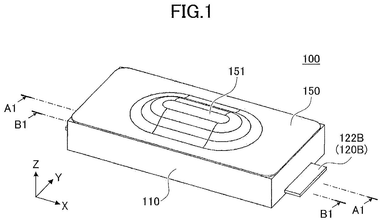
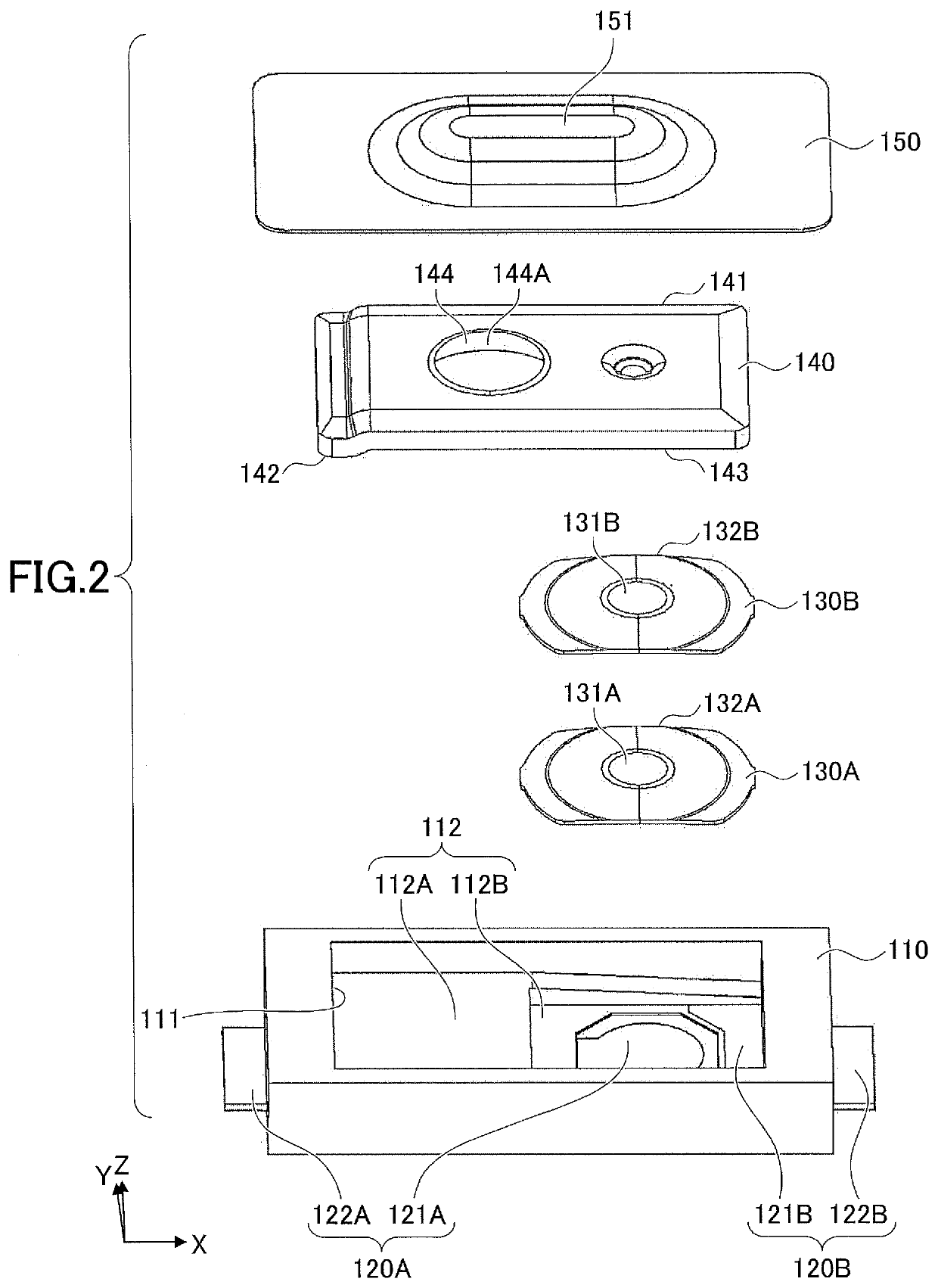
[0036]FIG. 1 is a perspective view of a push switch 100 according to a first embodiment. FIG. 2 is an exploded view of the push switch 100. In the following, an XYZ Cartesian coordinate system is used for description. Further, for convenience of description, the negative Z-side is referred to as a lower side or a lower part, and the positive Z-side is referred to as an upper side or an upper part, but this positional relationship does not represent a universal relationship.
[0037]The push switch 100 includes a housing 110, metal plates 120A and 120B, a metal contact 130A, a leaf spring 130B, a pressing member 140, and an insulator 150.
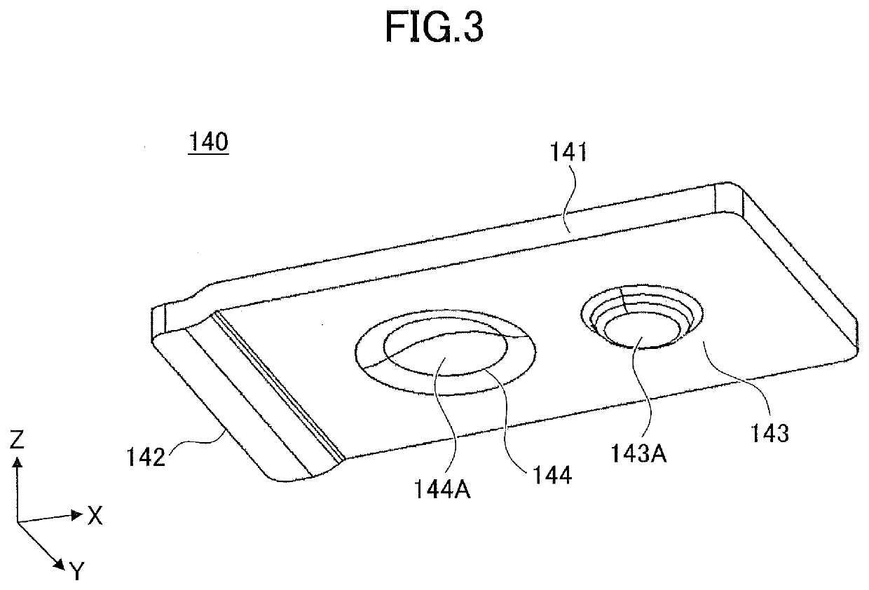
[0038]In the following, the pressing member 140 will be described with reference to FIG. 2 and FIG. 3. FIG. 3 is a diagram illustrating the back side of the pressing member 140. Further, a cross-sectional structure will be described with reference to FIG. 4 and FIG. 5. FIG. 4 is a cross-sectional view of the push switch 100 taken through A1-A1 of FIG. 1...
second embodiment
[0082]FIG. 7 is a perspective view of a push switch 200 according to a second embodiment. FIG. 8 is an exploded view of the push switch 200.
[0083]The push switch 200 includes a housing 210, metal plates 220A, 220B, and 220C, a metal contact 130A, a leaf spring 130B, and an insulator 150.
[0084]In the following, the pressing member 240 will be described with reference to FIG. 8 and FIG. 9, and the metal plates 220A, 220B, and 220C will be described with reference to FIG. 8 and FIG. 10. FIG. 9 is a diagram illustrating the back side of the pressing member 240. FIG. 10 is a diagram illustrating the structure of the metal plates 220A, 220B, and 220C. FIG. 10 depicts the housing 210 transparently. Further, a cross-sectional structure will be described with reference to FIG. 11A through FIG. 11C and FIG. 12A through FIG. 12C. FIG. 11A through FIG. 11C are cross-sectional views of the push switch 200 taken through A2-A2 of FIG. 7. FIG. 12A through FIG. 12C are cross-sectional views of the p...
third embodiment
[0110]FIG. 14 is a perspective view of a push switch 300 according to a third embodiment. FIG. 15 is an exploded view of the push switch 300.
[0111]The push switch 300 includes a housing 310, metal plates 320A and 320B, a metal contact 130A, pressing members 340A and 340B, a stem 350, and a frame 360. In the following, the pressing member 340B and the stem 350 will be described with reference to FIG. 14, FIG. 15, and FIGS. 16A and 16B. Further, the cross-sectional structure and the operation of the push switch 300 will be described with reference to FIG. 17, and FIG. 18. FIG. 17 and FIG. 18 are cross-sectional views of the push switch 300 taken through A3-A3 of FIG. 14.
[0112]Upon the stem 350 being pressed down, the metal contact 130A contacts the metal plate 320A, thereby causing the push switch 300 to be on (in an electrically connected state). A stroke for pressing the stem 350 in order to cause the metal contact 130A to contact the metal plate 320A is 0.1 mm, which is very short....
PUM
 Abstract
Description
Claims
Application Information
 - R&D
- Intellectual Property
- Life Sciences
- Materials
- Tech Scout
- Unparalleled Data Quality
- Higher Quality Content
- 60% Fewer Hallucinations
Browse by: Latest US Patents, China's latest patents, Technical Efficacy Thesaurus, Application Domain, Technology Topic, Popular Technical Reports.
© 2025 PatSnap. All rights reserved.Legal|Privacy policy|Modern Slavery Act Transparency Statement|Sitemap|About US| Contact US: help@patsnap.com