
Mobile training device

Active Publication Date: 2021-06-17
BLBW
View PDF18 Cites 0 Cited by
  • Summary
  • Abstract
  • Description
  • Claims
  • Application Information

AI Technical Summary

Benefits of technology

The invention is an exercising device that can be easily attached and fixed to a structure without needing additional tools. It has a hook-shaped recess that can be connected to a rod-shaped element, allowing users to exercise and treat different groups of muscles in their body. The device can be locked in multiple orientations, allowing for more flexibility in use. Additionally, the device is portable and easy to store and transport, making it more convenient for users.

Problems solved by technology

Shown to be disadvantageous thereby is that the connection of the exercising device to the supporting frame is complex.

Method used


Image

  • Mobile training device
  • Mobile training device
  • Mobile training device

Examples


first embodiment

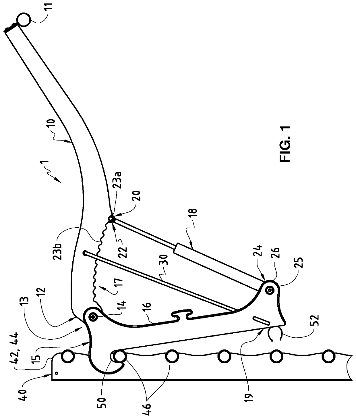
[0040]FIG. 1 shows in a side view the exercising device 1 according to the invention in combination with a structure 40 according to a This exercising device 1 comprises a power arm 10. This power arm 10 can be equipped on a free end region with an actuation element 11, for example, via which the power arm 10 can be actuated by an exercising person. At another end, the first end 12, the power arm 10 is provided at a first coupling point with a first articulated joint 13, via which the power arm 10 is connected to a retaining element 16 in an articulated way. In particular the power arm 10 is pivotable with respect to the retaining element 16 about a pivot axis or pin 14 on the first articulated joint 13.

[0041]The retaining element 16 can be designed as bow or bracket, whereby at a first end 15 of the retaining element 16 the first articulated joint 13 is disposed for connection of the power arm 10. The power arm 10 is furthermore connected by means of a resistance element 18 to the...

second embodiment

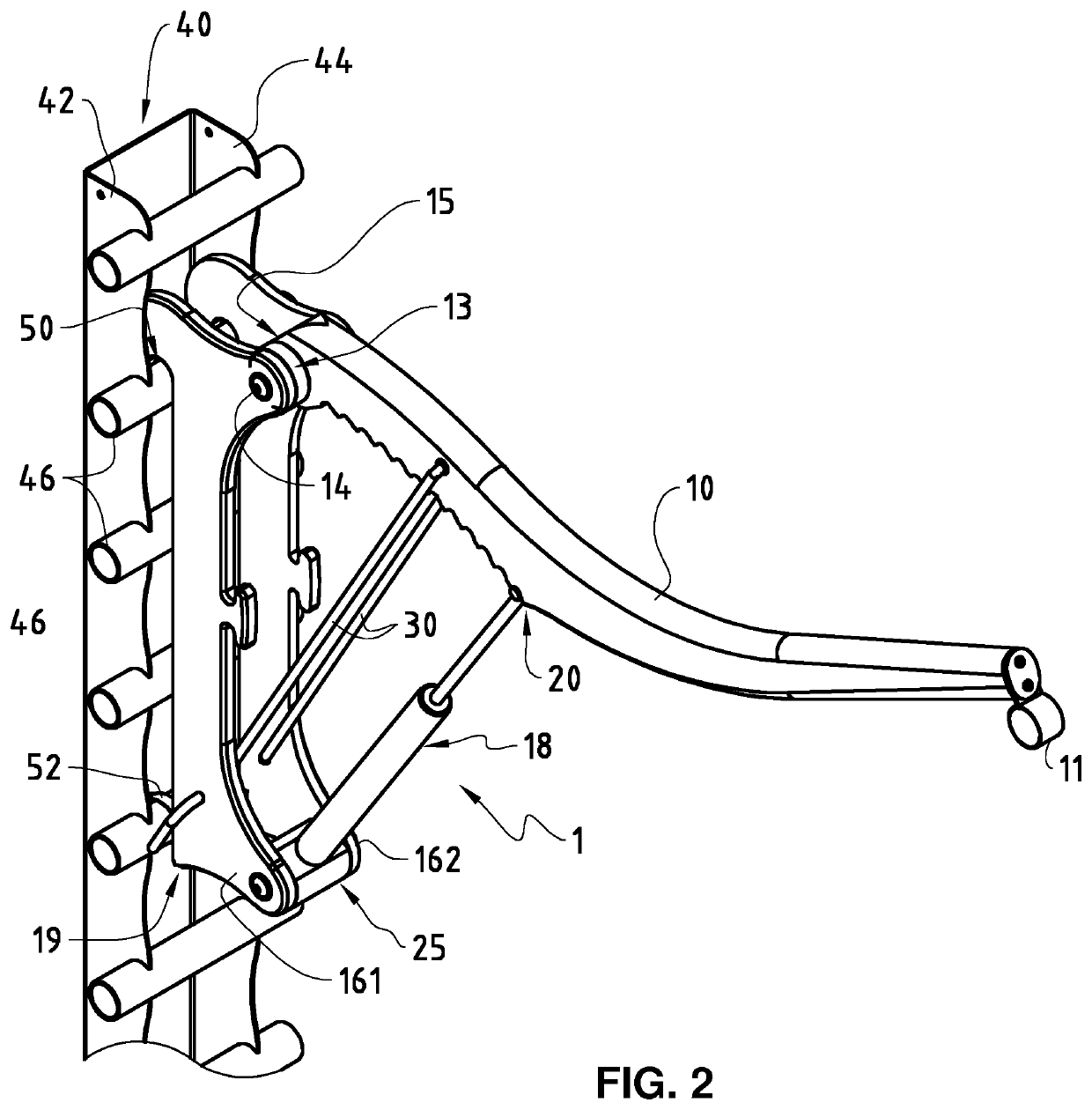
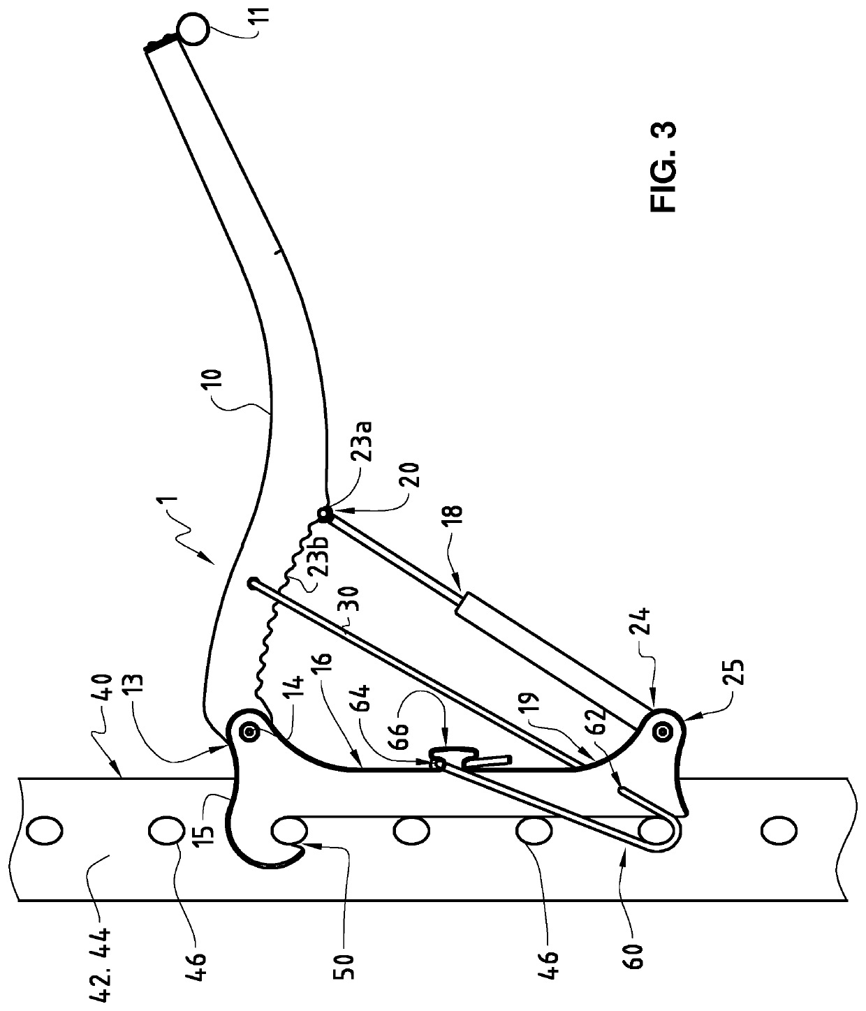
[0050]FIG. 4 shows a perspective view of the second embodiment according to FIG. 3. As in the case of commonly known gymnastic wall bars, the structure 40 comprises rungs, bars or respectively rod-shaped elements 46, disposed between side elements 42, 44. The exercising device 1 is hooked and locked on one of the rod-shaped elements 46 by means of the hook-shaped recess 50 provided on the first end 15. For fixing, the elastic elongated element 60, with its end 62 firmly connected to the retaining element 16, is wrapped around one of the rod-shaped elements 46 and is fixed at the second end 64 by means of the provided clamping device 66 in a more or less tensioned state. Preferably, elastic elongated elements 60 are provided on both sides of the retaining element 16.

[0051]In a preferred embodiment, the elastic elongated element 60 and the spring element 30 can be formed by a continuous cord or band, which is firmly connected to the power arm 10 at one end and is led through a through...


PUM


Abstract

The present invention relates to an exercising device (1) comprising a lever or power arm (10) which is able to be arranged by a first end (12) on a retaining element (16) at a first articulated joint (13) in a way pivotable about a pivot axis or pin (14), whereby a resistance element (18) is able to be coupled by a first end region (20) at a first coupling point (22) on the power arm (10), and by a second end region (24) at a second coupling point (26) at a second articulated joint (25) on the retaining element (16). The exercising device (1) is able to be detachably arranged on a structure (40) by means of an engaging connection, which is formed by a hook-shaped recess (50) and a rod-shaped element (46) and whereby the exercising device (1) is lockable in an engaged position by means of a fixation.

Description

TECHNICAL FIELD OF THE INVENTION[0001]The present invention relates to a mobile exercising device, in particular a mobile exercising device for exercising the muscles.STATE OF THE ART[0002]Exercising devices for exercising specific groups of muscles or muscles in general are available to users in fitness centers, in gymnasiums, in medical settings as well as also in the private sphere. As a rule, such apparatuses comprise a supporting frame installed in a fixed way on which a more or less convertible exercising device is disposed so that the user is provided with diverse application possibilities for exercising.[0003]Known from EP 0 146 274 is an exercising apparatus, which comprises a supporting structure which is mountable in a fixed way on a wall and is designed as a track on which an exercising unit is received in a slidable and detachable way. The exercising unit comprises for this purpose a correspondingly designed retaining element. The exercising unit further comprises a lev...

Claims


Application Information

Patent Timeline
IPC IPC(8): A63B21/16A63B21/00
CPCA63B21/169A63B21/0087A63B21/4047A63B21/16A63B23/1209A63B17/04A63B21/00072A63B21/1681A63B21/4019A63B21/4034A63B21/4035A63B23/03508A63B23/03525A63B23/0355A63B2071/0081A63B2208/0204A63B2210/06A63B2210/50A63B2225/093
Inventor SCHRAG, MICHAEL
Owner BLBW
Learn More