
Cardiac output control apparatus and method of use thereof

a control apparatus and output technology, applied in the direction of probabilistic networks, instruments, angiography, etc., can solve the problems of inability to remove reliably, mechanical devices and biomedical monitoring devices address a limited number of parameters,

Pending Publication Date: 2021-05-20
REICH ALTON +1
View PDF1 Cites 4 Cited by
  • Summary
  • Abstract
  • Description
  • Claims
  • Application Information

AI Technical Summary

Benefits of technology

The invention involves using fused data from a sensor to extract, filter, estimate, and / or add additional information about a system, and using this information to control the system, for example, a cardiac assist pump or a dosing pump. In simpler terms, this invention allows for better monitoring and control of a system using data from a sensor.

Problems solved by technology

Typical sources of noise and artifacts include baseline wander, electrode-motion artifacts, physiological artifacts, high-frequency noise, and external interference.
Some artifacts can resemble real processes, such as ectopic beats, and cannot be removed reliably by simple filters; however, these are removable by the techniques taught herein.
In addition, mechanical devices and biomedical monitoring devices address a limited number of parameters.

Method used


Image

  • Cardiac output control apparatus and method of use thereof
  • Cardiac output control apparatus and method of use thereof
  • Cardiac output control apparatus and method of use thereof

Examples


example i

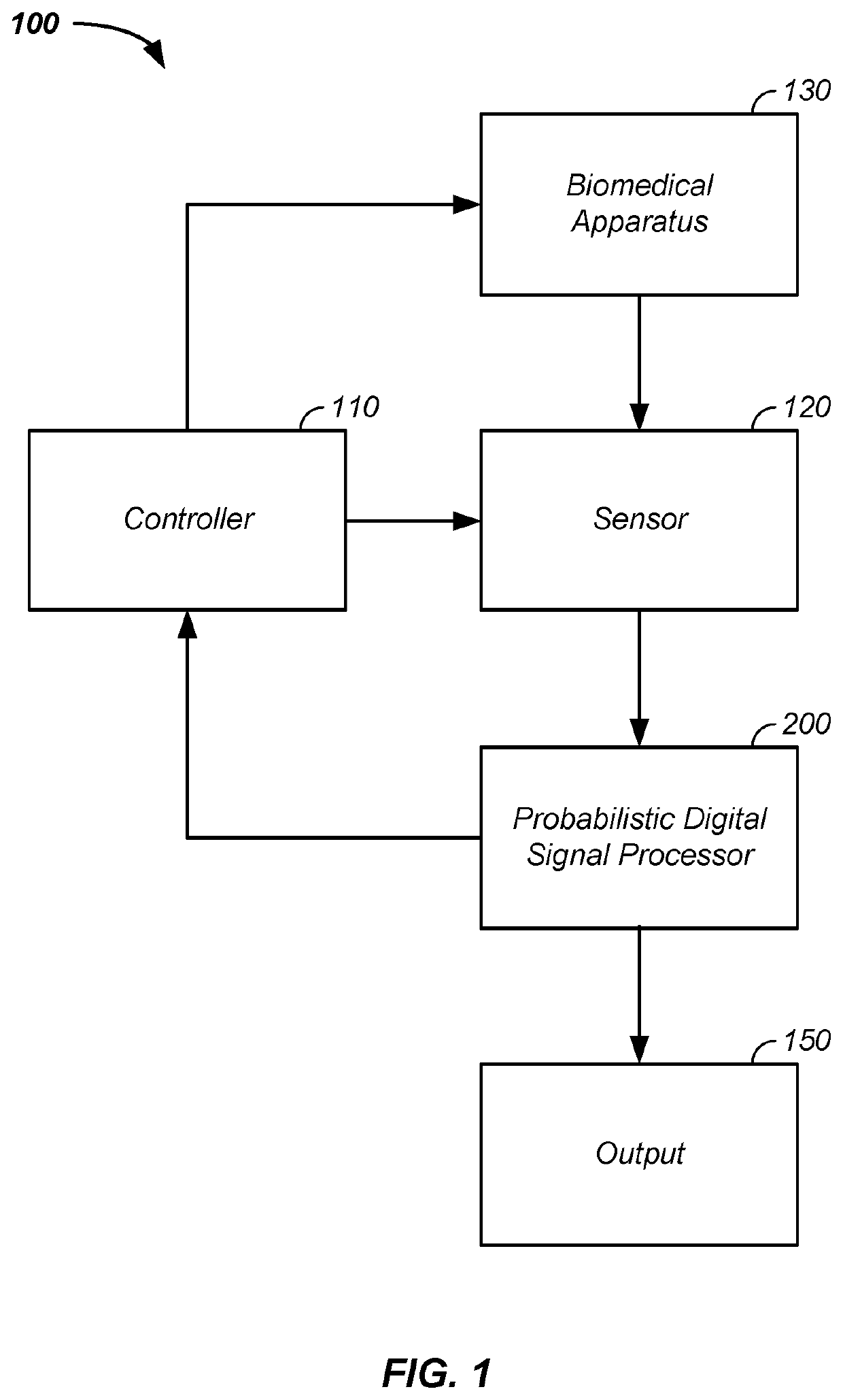
[0462]Referring now to FIG. 20B, a first example of the cardiac feedback control system 2000 is described. In this example, the cardiac monitor 110 monitors the person 112 and cardiac monitor output is provided as input to a cardiac assist pump 2022, which is an example of the controlled component 2020. The process is optionally and preferably repeated, such as in a closed control loop. The cardiac assist pump 2022 is optionally one or more of: a heart assist pump, a left ventricular assist device, and an electroactive polymer sleeve 2028. The heart assist pump and the left ventricular assist device are both commercially available. The electroactive polymer sleeve 2028 is further described, infra. Generally, the cardiac monitor 2010 includes the intelligent data extraction system 100, described supra, a cardiac output monitoring system 2012, and / or a cardiac output control system 2014. The cardiac output monitoring system 2012 monitors the cardiac state of the person 112, such as bl...

example ii

[0464]Referring now to FIGS. 20(A-C), an example of the cardiac feedback control system 2000 using a sensed state 2070 to adjust flow 2080 of blood in the person 112, such as via controlling the cardiac assist pump 2022 is described. Generally, the activity sensor 2016 is used to sense a state 2070 of the person 112. For instance, patterns of output as a function of time from the accelerometer 1510 are matched to a common activity, such as sleeping 2071, active movement 2072, walking 2073, climbing stairs 2074, or running 2075. Particularly, observed patterns include: a repeating shallow to no movement of x / y-position repeating in time matches sleeping 2071; a randomized change in x / y-position is indicative of active movement 2072 or active motion, where the degree of x / y-position change with time is a measure of a degree of activity; a repeating slow change in x / y-position with an intervening bump in z-axis position matches walking 2073; climbing stairs 2074 includes a larger net u...

example iii

[0466]In the prior two examples, the cardiac feedback control system 2000 altered the flow rate, such as a blood flow rate, of the person 112 to dynamically achieve a targeted flow rate, such as by adjusting the flow rate of the cardiac assist device / cardiac assist pump 2022, such as adjusting the flow rate at times exceeding every 0.5, 1, 2, 5, 10, 30, 60, or more seconds. Optionally, the cardiac feedback control system 2000 controls a dosing pump, where the delivered dosing agent increases or decreases a heart rate or blood flow rate. As dosing involves a response time, the cardiac feedback control system 2000 optionally and preferably alters the delivered dose at time intervals greater than 0.5, 1, 2, 6, 12, or 24 hours.


PUM


Abstract

The invention comprises an apparatus and a method for operating a cardiac assist pump, comprising the steps of: (1) providing a cardiac monitor comprising: a cardiac output sensor including an activity sensor and at least two of: a pulse oximeter; an electrocardiogram meter; and a blood pressure monitor; (2) receiving time-varying cardiovascular input data, from the cardiac output sensor, related to a transient hemodynamic state of a cardiovascular system; (3) receiving and operating on time-varying activity input data, from the activity sensor, to generate cardiovascular state information; (4) sensing activity with the activity sensor to generate a target cardiovascular state; (5) repeating both the steps of receiving and operating to update the transient cardiovascular state information and the step of sensing to update the target cardiovascular state; and (6) directing the cardiac assist pump to adjust assisted blood flow, yielding the updated transient cardiovascular state, toward the target cardiovascular state.

Description

CROSS-REFERENCES TO RELATED APPLICATIONS[0001]This application is:[0002]a continuation-in-part of U.S. patent application Ser. No. 16 / 533,778 filed Aug. 6, 2019, which is a continuation-in-part of U.S. patent application Ser. No. 15 / 251,779 filed Aug. 30, 2016, which is a continuation-in-part of U.S. patent application Ser. No. 13 / 181,140 filed Jul. 12, 2011, which is a continuation-in-part of U.S. patent application Ser. No. 13 / 181,027, filed Jul. 12, 2011, which:[0003]is a continuation-in-part of U.S. patent application Ser. No. 12 / 796,512, filed Jun. 8, 2010, which is a continuation-in-part of U.S. patent application Ser. No. 12 / 640,278, filed Dec. 17, 2009, which claims benefit of U.S. provisional patent application No. 61 / 171,802, filed Apr. 22, 2009;[0004]is a continuation-in-part of U.S. patent application Ser. No. 14 / 078,254 filed Nov. 12, 2013, which claims the benefit of U.S. provisional patent application No. 61 / 727,586;[0005]claims benefit of U.S. provisional patent appl...

Claims


Application Information

Patent Timeline
IPC IPC(8): A61M60/523A61B5/0205A61B5/029A61B5/11A61B5/1455A61B5/318A61B5/00A61M60/531A61M60/585A61M60/515G06N7/00G16H50/20G16H40/63
CPCA61M60/523A61B5/022A61B5/029A61B5/1118A61B5/14551A61B5/318A61B5/1123A61B5/4839A61M60/531A61M60/585A61M60/515G06N7/005G16H50/20G16H40/63A61B5/0205A61B5/02007A61B5/02108A61B5/02233A61B5/02255A61B5/7275A61B5/742A61B2560/0223G16H40/60G16H50/50G06N20/00A61M60/161A61M60/289A61M60/486A61M60/569A61M2230/63A61M5/1723A61M2205/0283A61M2205/3317A61M2205/3327A61M2205/50A61M2230/04A61M2230/06A61M2230/20A61M2230/205A61M2205/3306G06N7/01A61B2562/0219A61B2562/0223
Inventor REICH, ALTONROTH, MICHAEL
Owner REICH ALTON
Learn More