
Battery pack and power system comprising same

a battery pack and power system technology, applied in the direction of batteries, safety/protection circuits, cell components, etc., can solve the problems of ground voltage mismatch between the battery pack and the battery pack cannot communicate with the body of the electric powered device normally, and the manufacturing cost is higher than the required manufacturing cos

Active Publication Date: 2021-05-13
LG ENERGY SOLUTION LTD
View PDF0 Cites 1 Cited by
  • Summary
  • Abstract
  • Description
  • Claims
  • Application Information

AI Technical Summary

Benefits of technology

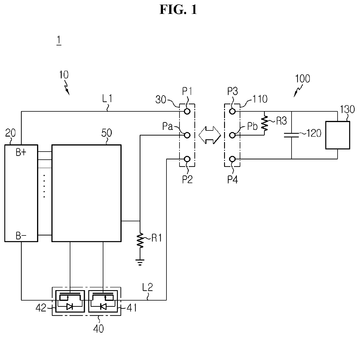
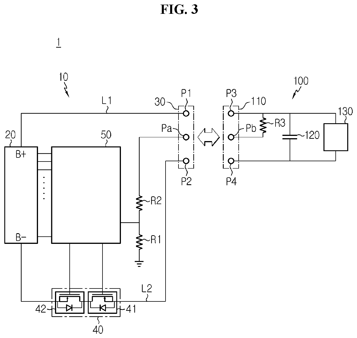
The present patent text describes a way to control a charge / discharge switch on the low side of a battery pack. The system uses a voltage division rule to determine if the switch is connected to an external device. Only when the switch is connected to the preset device, it will turn on and allow current to flow. This prevents accidental electrical shocks or spikes and ensures safe use of the battery pack.

Problems solved by technology

When the charge / discharge switch is installed on the high side of the battery pack, a charge pump and a gate driver are required, and accordingly it takes a higher manufacturing cost than the manufacturing cost required when the charge / discharge switch is installed on the low side of the battery pack.
Meanwhile, in case that the charge / discharge switch installed on the low side of the battery pack is turned off, when the battery pack is coupled to the body of the electric powered device, there is a ground voltage mismatch problem between the battery pack and the body of the electric powered device.
Accordingly, communication between the battery pack and the body of the electric powered device cannot be normally made, and it is difficult to properly turn on the charge / discharge switch.
To solve this problem, when the charge / discharge switch is always kept in turn on state, two power terminals of the battery pack are unintentionally electrically shorted, and there is a spike risk.

Method used


Image

  • Battery pack and power system comprising same
  • Battery pack and power system comprising same
  • Battery pack and power system comprising same

Examples


Embodiment Construction

[0027]Hereinafter, the preferred embodiments of the present disclosure will be described in detail with reference to the accompanying drawings. Prior to the description, it should be understood that the terms or words used in the specification and the appended claims should not be construed as limited to general and dictionary meanings, but interpreted based on the meanings and concepts corresponding to technical aspects of the present disclosure on the basis of the principle that the inventor is allowed to define terms appropriately for the best explanation.

[0028]Therefore, the embodiments described herein and illustrations shown in the drawings are just a most preferred embodiment of the present disclosure, but not intended to fully describe the technical aspects of the present disclosure, so it should be understood that a variety of other equivalents and variations could be made thereto at the time of filing the application.

[0029]Additionally, in describing the present disclosure...


PUM

PropertyMeasurementUnit
voltageaaaaaaaaaa
operating voltageaaaaaaaaaa
voltageaaaaaaaaaa

Abstract

Provided is a battery pack and a power system including the same. The battery pack includes a battery module having a positive electrode terminal and a negative electrode terminal, a first connector having a first power terminal connected to the positive electrode terminal, a second power terminal connected to the negative electrode terminal and a first auxiliary terminal, a first resistor having a first end electrically connected to ground and a second end electrically connected to the first auxiliary terminal, a switching unit installed between the negative electrode terminal and the second power terminal, and a control unit. The control unit is configured to operate in any one of a wakeup state and a sleep state according to a voltage of the first resistor.

Description

TECHNICAL FIELD[0001]The present disclosure relates to a battery pack and a power system including the same, and more particularly, to a battery pack for controlling electrical connection with an external device using the voltage division rule and a power system including the same.[0002]The present application claims priority to Korean Patent Application No. 10-2017-0135473 filed in the Republic of Korea on Oct. 18, 2017, the disclosure of which is incorporated herein by reference.BACKGROUND ART[0003]Recently, there is dramatically growing demand for portable electronic products such as laptop computers, video cameras and mobile phones, and with the intense development of electric vehicles, accumulators for energy storage, robots and satellites, many studies are being made on high performance secondary batteries that can be recharged repeatedly.[0004]Currently, commercially available secondary batteries include nickel-cadmium batteries, nickel-hydrogen batteries, nickel-zinc batteri...

Claims


Application Information

Patent Timeline
Patent Type & Authority Applications(United States)
IPC IPC(8): H01M10/42H01M50/597H01M50/204H01M50/543H01M10/46H01M10/44H02J7/00
CPCH01M10/425H01M50/597H01M50/204H01M50/543H01M2010/4271H01M10/441H02J7/0031H02J7/0013H01M2200/30H01M10/46H02J7/0036H02J7/0029H01M2200/00Y02E60/10H01M50/574H01M10/4257H02J9/005H01M2010/4278H01M2220/30A47L2201/022
Inventor KIM, HAK-INKIM, DONG-HYUNNAM, HO-CHOL
Owner LG ENERGY SOLUTION LTD
Learn More