Relative rotation prevention structure for screw, relative movement prevention structure, and relative movement prevention body

a technology of relative rotation and prevention structure, applied in the direction of threaded fasteners, fastening means, screws, etc., can solve the problems of shaft breakage, ratchet structure breakage, etc., and achieve the effect of reliable anti-loosening effect and reduced shaft fatigu

Pending Publication Date: 2021-05-13
NEJILAW
View PDF13 Cites 1 Cited by
  • Summary
  • Abstract
  • Description
  • Claims
  • Application Information

AI Technical Summary

Benefits of technology

[0009]In view of the above problems, the present disclosure is to provide a screw rotation prevention structure, which may exhibit a reliable anti-loosening effect, and reduce fatigue of the shaft of the male screw and, in addition, disallow a mating state of the male and female fastening mechanisms without destroying the fastening member itself such that they are separated from each other.
[0010]Further, the present disclosure is to provide a structure for preventing relative movement in not only a screw but also relative movement between a first member and a second member.
[0032]The relative-rotation prevention structure is characterized in that the screw-side deformation-capable section of the screw has low rigidity compared to the counterpart-side displacement section of the counterpart member.
[0052]In accordance with the present disclosure, the screw rotation prevention structure may exhibit a reliable anti-loosening effect, and reduce fatigue of the shaft of the male screw.
[0053]Further, in accordance with the present disclosure, the structure may prevent relative movement not only in a screw but also relative movement between a first member and a second member.

Problems solved by technology

However, when it is necessary to loosen the female threaded bodies after the fastening, it is necessary to break the ratchet structure.
Further, in the structure of Patent Document 2, the pair of female threaded bodies may act a shear force acting on a shaft portion of the male screw permanently such that the shaft portion may be fatigued locally, and thus shaft breakage may occur at the local position.

Method used


Image

  • Relative rotation prevention structure for screw, relative movement prevention structure, and relative movement prevention body
  • Relative rotation prevention structure for screw, relative movement prevention structure, and relative movement prevention body
  • Relative rotation prevention structure for screw, relative movement prevention structure, and relative movement prevention body

Examples


first embodiment

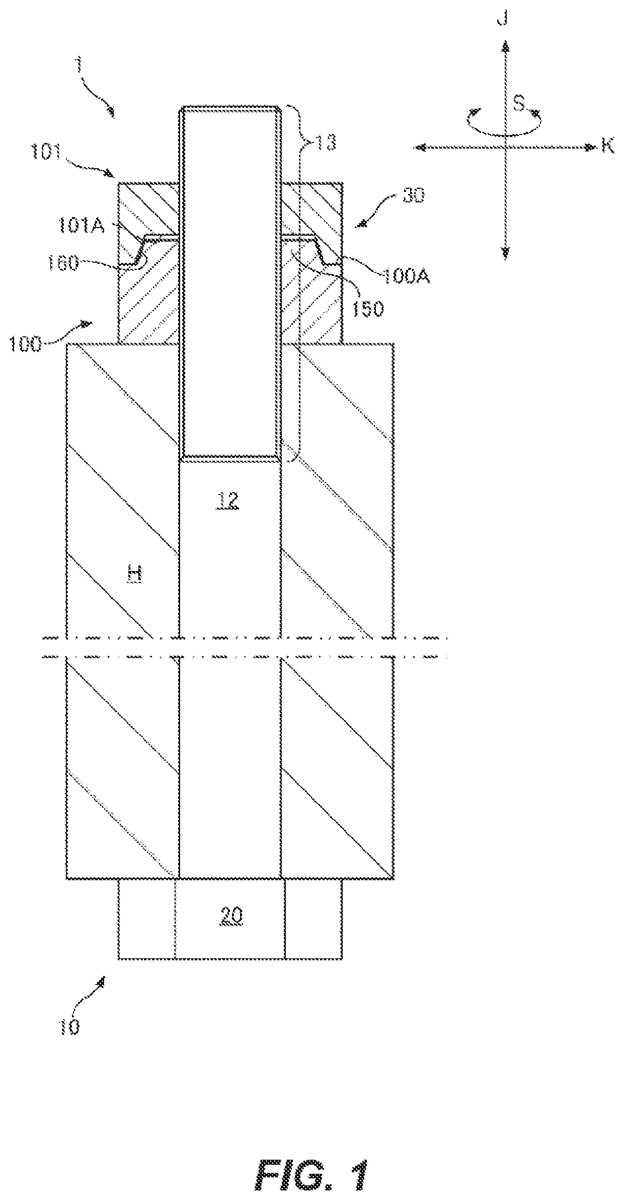
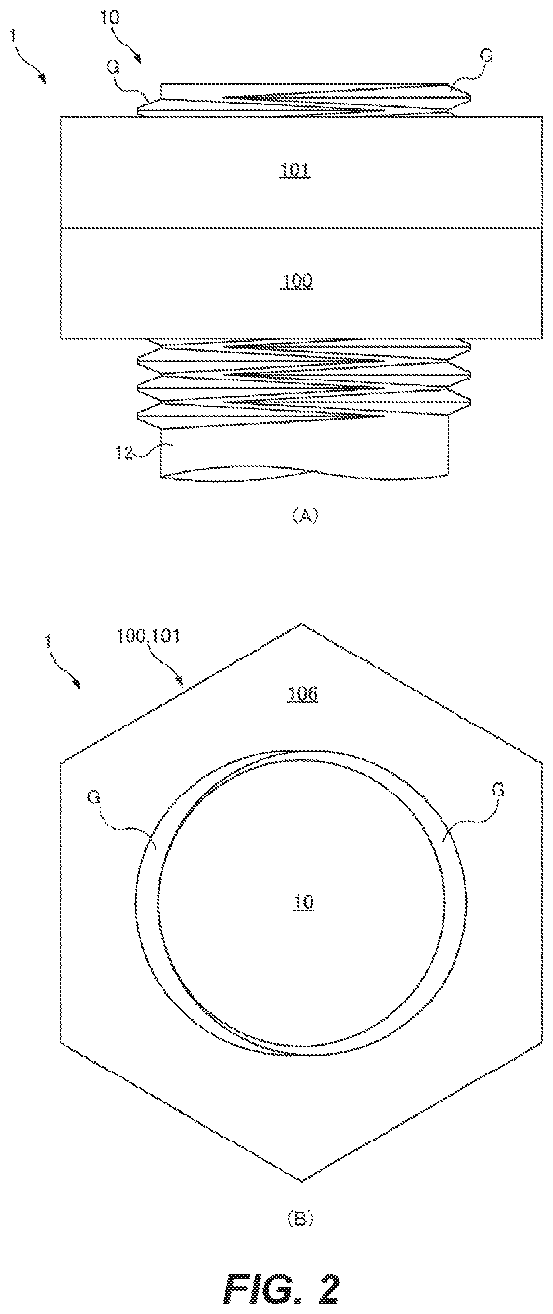
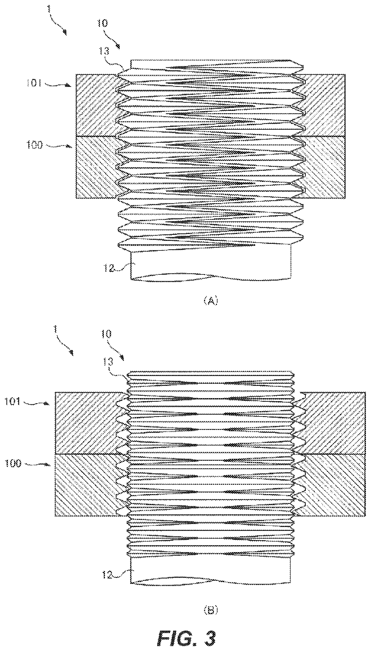
[0108]FIG. 1 shows a screw-based fastening mechanism 1 to which a relative-rotation prevention structure 30 according to the present disclosure is applied. The screw-based fastening mechanism 1 includes a first female screw 100, a second female screw 101, and a male screw 10. The screw-based fastening mechanism 1 may fasten a fastening target member H. In the present embodiment, the first female screw 100 and the second female screw 101 adjacent thereto outwardly in an axial direction constitute a so-called double nut structure such that they prevent from loosening from each other. The relative-rotation prevention structure 30 is provided between the first female screw 100 and the second female screw 101.

[0109]A basic structure of the screw-based fastening mechanism 1 will be described. As shown in (A) of FIG. 5, in a male threaded portion 13 of the male screw 10, two types of male threaded spiral grooves including a first spiral groove 14 formed as a right direction screw configure...

second embodiment

[0166]In this second embodiment, as shown in FIG. 17, an entirety of the annular concave portion 160 becomes the second (screw-side) deformation-capable section 50. Therefore, using a fastening force when the first female screw 100 and the second female screw 101 approach each other, this second deformation-capable section 50 presses the first displacement section 40 of the first female screw 100 and thus is deformed so that a portion thereof is depressed outwardly in the radial direction. This deformation produces the second (screw-side) displacement section 60. Further, in FIG. 20, the second displacement section 60 is not produced because FIG. 20 shows a state before fastening.

[0167]The second deformation-capable section 50 of the second female screw 101 is made of a flexible material, compared to the first displacement section 40 of the first female screw 100. Further, the second deformation-capable section 50 has low rigidity compared to the first displacement section 40. In th...

third embodiment

[0195]In FIG. 31, there is shown an engagement mechanism 235 to which a relative-movement prevention structure 230 of a third embodiment is applied. This engagement mechanism 235 includes a first member 200 and a second member 201. In this embodiment, a first face 200A is formed on the first member 200, while a second face 201A is formed on the second member 201. When the two faces are brought into contact with each other and pressed against each other, the relative-movement prevention structure 230 is produced such that relative movement in the plane direction between the first member 200 and the second member 201 is prevented. Therefore, the engagement mechanism may be used for a so-called anti-slip, a brake, a positioning mechanism, etc. Further, in this embodiment, the first face 200A and the second face 201A become flat. The present disclosure is not limited thereto. The faces may be a curved face, a bent face, or an uneven surface.

[0196]The relative-movement prevention structu...


PUM


Abstract

A relative rotation prevention structure for preventing relative rotation of a screw having a threaded section with respect to a counterpart member, the relative rotation prevention structure being equipped with: a counterpart-side displacement section formed in advance on the counterpart member and capable of displacement in the axial direction or the radial direction; and a screw-side deformation-capable section that is formed on the screw and deforms when pressed into the counterpart-side deformation section by means of fastening force and, due to that deformation, produces a screw-side displacement section that is displaced in the axial direction or the radial direction.

Description

CROSS-REFERENCE TO RELATED APPLICATIONS[0001]This application is a national phase entry under 35 U.S.C. § 371 of International Patent Application PCT / JP2018 / 010925, filed Mar. 20, 2018, designating the United States of America and published as International Patent Publication WO 2018 / 180737 A1 on Oct. 4, 2018, which claims the benefit under Article 8 of the Patent Cooperation Treaty to Japanese Patent Application Serial No. 2017-060816, filed Mar. 27, 2017, Japanese Patent Application Serial No. 2017-100636, filed May 22, 2017, and Japanese Patent Application Serial No. 2017-131553, filed Jul. 4, 2017.TECHNICAL FIELD[0002]The present disclosure relates to a structure for preventing relative rotation of a screw with respect to a counterpart member.BACKGROUND[0003]Conventionally, one of fastening structures includes a male screw such as a bolt, and a female screw such as a nut. In a fastening structure using this screw type, two types of spiral grooves having different lead angles and...

Claims


Application Information

Patent Timeline
Patent Type & Authority Applications(United States)
IPC IPC(8): F16B39/12
CPCF16B39/12F16B39/16F16B2033/025F16B39/36F16B39/34
Inventor MICHIWAKI, HIROSHI
Owner NEJILAW
Why Eureka
Try Eureka