
Bone growth stimulator and methods of use

a growth stimulator and bone technology, applied in the field of bone growth stimulators, can solve the problems of no one that can change the shape or form of cortical bone without aggressive surgical intervention, and achieve the effects of restoring bone shape in bone deformity and deficient areas, extending the biological envelope, and expanding range and distan

Pending Publication Date: 2021-05-06
NEW YORK UNIV
View PDF8 Cites 0 Cited by
  • Summary
  • Abstract
  • Description
  • Claims
  • Application Information

AI Technical Summary

Benefits of technology

The present invention is a new treatment method for treating skeletal defects by stimulating cortical bone formation in the desired direction using a minimally invasive method. This allows for non-surgical correction of severe malocclusions and other skeletal deformities. The device and method can be used to expand the biological envelope, range, and distance to which teeth can be moved orthodontically, change the shape of craniofacial bones, and stimulate new bone formation and cortical drift. The invention is the first method to address the challenges in adult dentofacial orthopedic treatment for non-growing patients.

Problems solved by technology

While there are non-invasive methods to increase trabecular bone density, there are none that can change the shape or form of cortical bone without aggressive surgical intervention.

Method used


Image

  • Bone growth stimulator and methods of use
  • Bone growth stimulator and methods of use
  • Bone growth stimulator and methods of use

Examples


example 1

Periosteal Stimulation Causes Cortical Bone Formation

[0056]As noted above, there is an enormous need for a technique that can stimulate bone formation at the surface of cortical bone, non-invasively to be able to expand the limit of orthodontic dental corrections.

[0057]To address this challenge, in the first series of experiments, rats (5 per group) were exposed to orthodontic transverse forces, applied to the upper molars and pushing towards the cortical bone (FIGS. 9A and 9B). After 56 days the animal were sacrificed and micro-CT images were collected. FIGS. 10A and 10B are micro-CT images of a control (no expansion) (FIG. 10A) and expansion (FIG. 10B) subjects collected after 56 days. In response to orthodontic forces, teeth were moved towards the cortical bone (FIG. 10B). As shown, the bone did not follow the tooth and, therefore, bone loss around the roots of the tooth was apparent (FIG. 10B, top panel) and the cortical plate became thinner (FIG. 10B, bottom panel).

[0058]In a s...

example 2

Periosteal Stimulation with Delivery of Exogenous Growth Factor Causes Synergistic Cortical Bone Formation

[0059]One possible reason for this stimulation may be the local release of growth factors in the area. Therefore, in another series of experiments, animals were divided into 3 groups: 1) control that did not receive any treatment; 2) animals that received injection of PDGF once per week (around first molar area); and 3) animals that received periosteal stimulation once per week in a similar area. No orthodontic force was applied to these animals / teeth. Compared to control (FIG. 15A), the group that received injection of PDGF did not show significant bone formation (FIG. 15B) while the group that received periosteal stimulation demonstrated significant bone formation (FIG. 15C). These results indicate that the endogenous release of growth factors in response to periosteal stimulation is more effective to stimulate bone formation than injection of exogenous growth factors.

[0060]To...


PUM

PropertyMeasurementUnit
Lengthaaaaaaaaaa
Lengthaaaaaaaaaa
Contentaaaaaaaaaa

Abstract

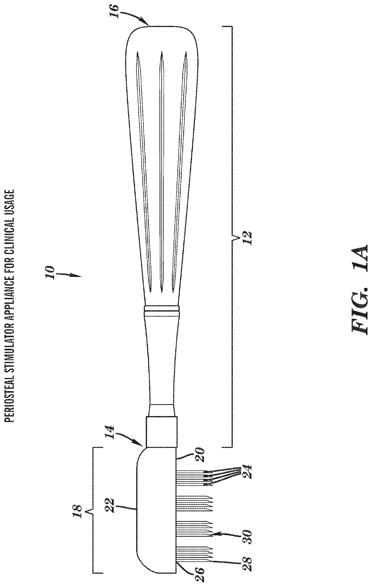
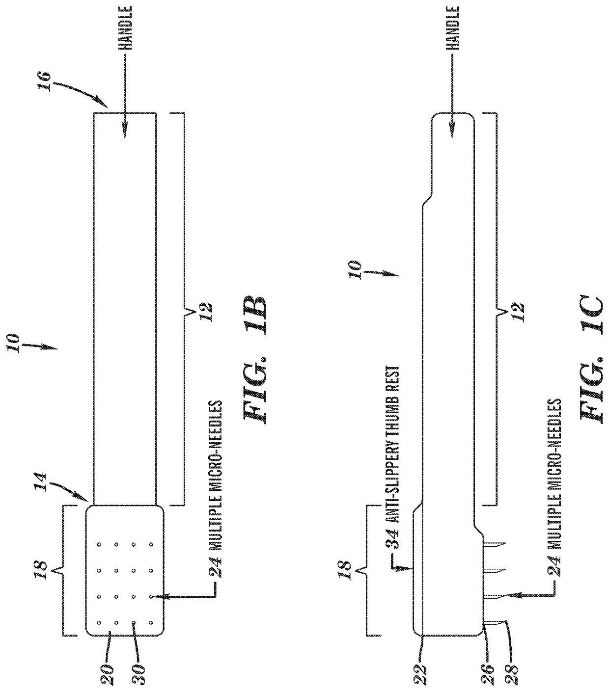
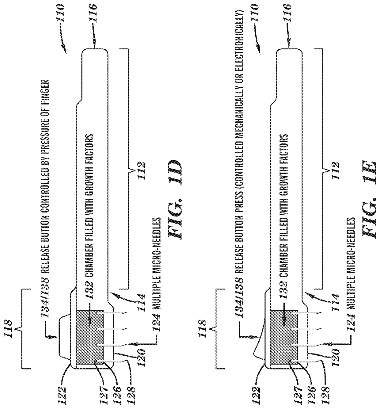
The present invention relates to a device. The device includes an elongate handle having a proximal end and a distal end; a head portion extending from the proximal end of the elongate handle, the head portion having a first interior-facing surface and an opposing second exterior-facing surface; and a plurality of microneedles extending from, and perpendicular to, the first interior-facing surface of the head portion. Each of the plurality of microneedles has a base connected to the first interior-facing surface of the head portion and a free tip end. The present invention also relates to a method for stimulation of cortical bone formation using the device of the present invention.

Description

[0001]This application claims priority benefit of U.S. Provisional Patent Application No. 62 / 546,799, filed Aug. 17, 2017, which is hereby incorporated by reference in its entirety.FIELD OF THE INVENTION[0002]The present invention relates to devices and methods of their use in stimulating bone formation.BACKGROUND OF THE INVENTION[0003]One of the main challenges in orthodontics relates to the cortical bone that surrounds the alveolar bone. This bone acts as an envelope that determines the limit to which a tooth can be moved safely. Since cortical bone does not follow the moving tooth, any movement towards that cortical plate may push the tooth out of the bone envelope. This may cause bone loss around the tooth, which can jeopardize the long term prognosis of the tooth. To compensate for this limitation, many extensive and expensive surgical approaches have been proposed to cut the bone and tooth together as a segment and move the tooth and the surrounding cortical bone surgically. D...

Claims


Application Information

Patent Timeline
IPC IPC(8): A61M37/00A61C19/06
CPCA61M37/0015A61C19/063A61M2202/07A61M2037/0023A61M2037/003A61C19/06A61B17/3472A61B17/205A46B11/002A61M5/3202
Inventor ALIKHANI, MANITEIXEIRA, CRISTINASANGSUWON, CHINAPAALANSARI, SARAHOLIVEIRA, SERAFIMROQUE, CANDIDO
Owner NEW YORK UNIV
Learn More